
Summary of Teardown and experiments with a Doppler microwave transceiver
This article details a teardown of the Microsemi C900502 10.525 GHz X-band Doppler radar motion sensor. The module features a sturdy metal casing with integrated patch antennas on the PCB. It requires only three connections: +5V, ground, and IF output. Internally, the device uses a simple design with five discrete components, including an FET oscillator, a dielectric resonator, and distributed element filters like radial stubs. The internal shielding separates the oscillator and mixer compartments to prevent leakage.
Parts used in the C900502 Teardown:
- Metal casing
- PCB with patch antennas
- Adjustment hole
- Screwdriver
- Oscillator compartment
- Mixer compartment
- RF absorbing strips
- Circuit board
- FET (Field Effect Transistor)
- Dielectric resonator
- Distributed element filters
- Radial stubs
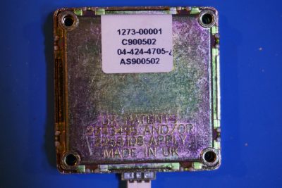
I got a couple of Microsemi’s C900502 10.525 GHz X-band Doppler radar motion sensors a while ago. This batch was made in UK and had “UK patents 2243495 and/or 2253108 apply” printed on the case. I have seen a teardown of an HB100 Doppler radar module before and was wondering if I this one is any different inside.
The C900502 transceiver has a very sturdy metal casing. It is measured at roughly 5cm by 5cm by 1cm. The transmitter and receiver antennas are patch antennas etched directly onto the PCB as you can see from the picture below:
On the back side you can see the patent number stamped onto the casing. There is an adjustment hole underneath the model number sticker. Using a screw driver, you can make fine adjustments of the transmitted frequency. Using this module is simple and only three connections are required: +5V, ground, and IF output.
Here is a picture of the back shielding removed. The shielding is divided into two compartments, one for the oscillator and the other houses the mixer. You can see some RF absorbing strips inside the oscillator compartment, this is to reduce the oscillator leakage into the mixer.
And here is a picture of the circuit board. It is surprisingly elegant, only 5 discrete components (two active components and three passive components) are used. The board layout is strikingly similar to that of HB100. Perhaps HB100 is based on the same patents?
Here is a closeup of the oscillator portion. The oscillator consists of a single FET. The brown cylindrical component is a dielectric resonator. Note that it is not physically connected to any other components. The coupling is achieved strictly via the electromagnetic fields outside the cylindrical boundary of the dielectric resonator. The resonant frequency (TE01n mode) of the dielectric resonator can be calculated as:

 r
r aL+3
aL+3 45
45
where the relative permittivity of the dielectric material is usually between 30 and 50. Barium titanate (BaTiO3) is a common material used for the dielectric resonator.
You can also see many distributed element filters on the PCB. Here you can see two radial stubs.
Read more: Teardown and experiments with a Doppler microwave transceiver
-
What are the required connections for using the C900502 module?
Only three connections are required: +5V, ground, and IF output. -
How is the transmitted frequency adjusted on this module?
You can make fine adjustments using a screwdriver through an adjustment hole located underneath the model number sticker. -
What material is commonly used for the dielectric resonator in the oscillator?
Barium titanate is a common material used for the dielectric resonator. -
How does the coupling work between the dielectric resonator and other components?
The coupling is achieved strictly via electromagnetic fields outside the cylindrical boundary of the dielectric resonator. -
Why are RF absorbing strips placed inside the oscillator compartment?
These strips are used to reduce oscillator leakage into the mixer. -
How many discrete components are used on the circuit board?
There are only five discrete components used, consisting of two active components and three passive components. -
Are the antennas on the C900502 separate or integrated?
The transmitter and receiver antennas are patch antennas etched directly onto the PCB. -
What is the purpose of the internal shielding compartments?
The shielding is divided into two compartments, one for the oscillator and the other houses the mixer.
