Summary of The KIM Uno – a 5€ Microprocessor Dev Kit Emulator
The KIM Uno is a portable, low-cost microprocessor development kit that emulates CPUs like the 6502 or OISC subleq using an ATMega328p. Designed to fit in one hand and powered by two CR2032 batteries, it allows users to build a retro dev environment for under €5. The project involves sourcing a custom PCB, soldering standard components, and programming the device via an ISP programmer to create a versatile emulation platform.
Parts used in the KIM Uno:
- 7x 1 kΩ resistors
- 1x 10 kΩ pull-up resistor
- 1x 100nF capacitor
- 1x ATMega328P (DIP-28 package)
- Main PCB
- 2x CR2032 battery holders
- 1x SPDT switch
- 20x SMD tactile push buttons
- 1x 1x6 pin header (optional)
- 1x four-digit seven segment display
- 1x two-digit seven segment display
The KIM Uno is a portable, software defined dev kit for (retro) microprocessors. But let me introduce the idea of it by going back in time:
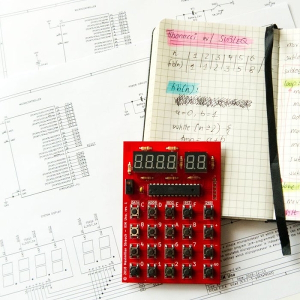
Back in late 2018 it came to my mind, that I wanted to build a small portable microprocessor dev kit, just like the famous KIM-1 from MOS Technology, Inc. and designed by Chuck Peddle who was also involved in creating the 6502 CPU.
But building a “bare-bone” dev kit with discrete logic components was no option since it needed a big power supply (since those ancient devices tend to take some serious current) and also the development would be very time intensive. And I want it now!
Therefore, I designed the KIM Uno as a portable device, which fits in one hand and is powered by two CR2032 batteries. It uses the ATMega328p (“Arduino”) microcontroller running at 8 MHz to emulate (or simulate) a desired CPU. This architecture also makes sure, that the emulated CPUs are interchangeable to anything which fits inside the microcontroller’s flash memory. So it is a multi-purpose device.
By coincidence I later watched a really good talk – called The Ultimate Apollo Guidance Computer Talk (34C3) – on YouTube where “One Instruction Set Computers” or OISCs are mentioned. I did not know about them and found this as the perfect candidate to implement it.
The KIM Uno emulates a CPU with just one instruction: subleq – subtract and branch if less than or equal to zero.
If you follow along with me through this Instructable, you can build your own KIM Uno in no time. And the best part – beside the fact that you can modify it to your taste – is, that it only costs 4,75 € to make (as of end 2018).
One hint: there is a Git repository which contains all the files provided by the different steps of this instructable. In case you want to modify some resources and share them with us all you can make a PR. But you can also download all files at once there. Simply to to https://github.com/maxstrauch/kim-uno. Thanks!
There is another pretty interesting project, called the same (KIM Uno), which does a real replica of the 6502 KIM Uno. Check it out here. The creator even sells the kit. So if you are interested in 6502 and like this project, you should take a look there!
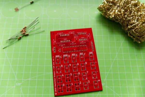
Step 1: Sourcing the PCB
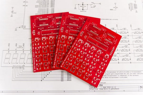
As you can see, I used the opportunity to design a PCB and let it be professionally made. Since manufacturing it externally and shipping it to you will take a lot of time (depending on where you are in the world 😉 ), getting it ordered it is the first step. We can then continue with the other steps while the PCB is made and shipped to you.
I ordered my PCBs in China at PCBWay for just $5. I don’t get any benefit for presenting PCBWay as my goto manufacturer for PCBs, it’s just that it worked fine for me and might also work fine for you. But you can order them at any other place like JLCPCB, OSH Park or any local PCB company.
But if you are willing to order them at PCBWay you can download the attached ZIP file “kim-uno-rev1_2018-12-12_gerbers.zip” and upload it directly to PCBWay without any change. This is the original file I used to order the PCBs you can see in the images.
If you are ordering them from an other manufacturer you might need to re-export them from the original KiCad sources, because I generated them with the specifications from PCBWay you can find here. For the original KiCad sources, download “kim-uno-kicad-sources.zip” and extract it.
But there is even a second way: if you don’t want to order the PCB, you can build your own version using perfboard or even a breadboard.
Anyway: since the PCBs are now on the way, we can focus on the other parts! Come, follow me.
Step 2: Sourcing the Components
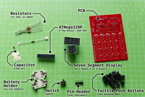
Now you need to get the components. For this you’ll find an overview image of all components and quantities you need, attached to this step as well as a BOM (bill of materials).
The BOM contains links to eBay. Although those offers might be closed when you read this, you can use it as a starting point. The used components are pretty standard.
In the following I’ll explain to you all the needed components:
- 7x 1 kΩ resistors for the seven segment displays. You can reduce the value (e.g. to 470 Ω) to make them shine brighter, but reduce it not too much otherwise the LEDs will die or the battery is drained very quickly. I found that this value works for me
- 1x 10 kΩ as a pull-up resistor for the RESET line of the microcontroller
- 1x 100nF capacitor to smooth out any voltage spikes (which should not happen since we are using batteries, right, but for good measure …)
- 1x ATMega328P in the DIP-28 package (usually named ATMega328P-PU)
- 1x the main PCB – see the previous step; either ordered or built by yourself
- 2x CR2032 battery holders
- 1x SPDT (single pole, double throw) switch which basically has three contacts and in every of its two states (either on or off) it connects two contacts
- 20x tactile push buttons for the keyboard. To use the backside of the PCB I used SMD tactile push buttons (the standard 6x6x6 mm ones) – they are pretty easy to solder as you will see
- OPTIONAL: 1x 1×6 pin header for connecting the programmer, but this is optional as you will see later
- 1x seven segment display with 4 digits and 1x seven segment display with 2 digits – the board will take only 0.36 inch (9,14 mm) elements with common anode wiring. Both requirements are important in order to get a working unit. But also this type of seven segment display are very common
Attached to this step you can find the file “component-datasheets.zip” which contains more precise information on dimensions and types of the used components. But most of the components are very standard and can be sourced easily for little money.
Now you need to wait until you have all components ready to continue to soldering. During this time you can already jump to the end and read a little bit about using the KIM Uno if you like.
Step 3: Soldering Tool Overview
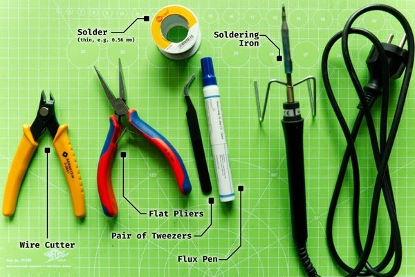
For soldering and building the KIM Uno you need the tools shown by the images:
- Wire cutter (to cut the end of the component wires)
- Flat pliers
- Pair of tweezers
- (decent) Solder which is not to thick – I use 0.56 mm solder
- A soldering iron – you don’t need a high-end soldering iron (because we are also not doing rocket science here) – I use the Ersa FineTip 260 for a long time now and it is really good
- A flux pen: adding flux to the components and pads makes it so much more easier to solder them since the solder then “flows” by its own to the right place*
- Optionally: a sponge (from metalwool) for your soldering iron
To later program the KIM Uno you’ll also need:
- a computer with the AVR-GCC toolchain and avrdude to upload the firmware
- an ISP (programmer) – as you can see on the image I’m using my Arduino Uno as an ISP with a special sketch – so no need to buy any fancy hardware
* some guidance by humans needed 😉
Are you ready? In the next step we are going to start assembling the KIM Uno.
Step 4: Soldering #1: Adding Resistors and Capacitors
You should always work from the smallest (in terms of component height) components first, to the highest components last. Therefore, we start by adding the resistors and bending over the legs at the back so that the resistors are easy to solder and stay in place. Afterwards cut the long wires.
Also, not shown in the images, add the small 100 nF capacitor the same way.
One tip: keep those wire legs in a small container, they sometimes come in handy.
Source: The KIM Uno – a 5€ Microprocessor Dev Kit Emulator
- How is the KIM Uno powered?
The device is powered by two CR2032 batteries. - What microcontroller does the KIM Uno use?
It uses an ATMega328p running at 8 MHz. - Can the KIM Uno emulate different CPUs?
Yes, it can emulate any CPU that fits inside the microcontroller's flash memory. - What specific instruction set does the KIM Uno emulate?
It emulates a One Instruction Set Computer using the subleq instruction. - What is the estimated cost to build the KIM Uno?
The project costs approximately 4.75 € as of late 2018. - Do I need a dedicated programmer to build the KIM Uno?
No, you can use an Arduino Uno as an ISP programmer. - What type of seven segment displays are required?
You need common anode displays with 0.36 inch elements. - Where can I find the source files for the project?
All files are available in the Git repository at https://github.com/maxstrauch/kim-uno.