
Summary of TORPEDO: an all-purpose switched-mode power supply
The article details the practical implementation of "Torpedo," a SEPIC-based switched-mode power supply designed to replace underperforming linear regulators in Arduino boards. It features triple power inputs (USB, battery, external), a wide input voltage range (3-20V), and high efficiency. The project includes an integrated LiPo charger and seamless source switching to ensure a stable 5V output with low ripple.
Parts used in the Torpedo:
- D5 Diode
- D6 Diode
- Q1 MOSFET
- Internal protection diode within the MOSFET
- U2 VIN pin
Having explained the theory, let’s see in practice the project of the SEPIC power supply.
In this post we discussed – on a theoretical level (even if in a simplified way) – the SEPIC switching converters, also highlighting advantages and disadvantages, and giving you the basics for the calculation of their components. Let’s get to the heart of the project, now; we will present a practical application of the previously explained concepts: a power supply that we named Torpedo. It is a switched-mode power supply with a SEPIC configuration, that was born in order to execute some tests finalized to substitute – when we were developing our Fishino UNO board – the underperforming linear regulator that was found in it, and in all Arduino boards. The features that we wanted were: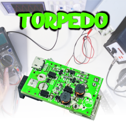
- triple power source, that is to say: the USB, the battery and an external one;
- wide range of values as for the input voltage: from 3 to 20 volts;
- minimum output current of 500 mA, with the possibility to reach 1A and more, via an external source;
- high efficiency, above 70% and possibly above 80-90%;
- single-cell LiPo battery charger incorporated;
- a transition from battery power to another source that is without interruptions;
- 5 V output with high stability, having a low ripple and when varying the load.
As we will see later, all the project specifications have been respected in Torpedo.
Circuit Diagram
In order to better understand our circuit’s functioning, we may divide the diagram in three blocks:
- input stage;
- battery charger;
- SEPIC converter.

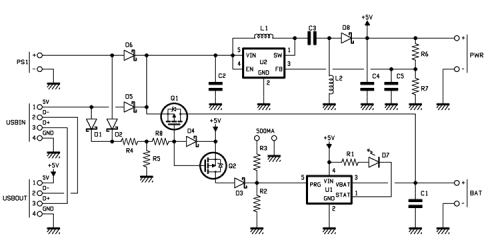
The input stage is composed mainly of the D5 and D6 diodes, that coupled with the Q1 MOSFET form the power source selector.
We will momentarily neglect the Q1 MOSFET and deal only with the D5 and D6 diodes and with the protection diode that is internal to the MOSFET itself: the three voltages – coming from an equal number of inputs, BAT, USBIN and PS1 – directly polarize the three diodes and therefore tend to make them start to conduct, reaching up to U2’s VIN pin. Clearly, the greatest voltage among the three of them brings the diode to conduct and causes the interdiction of the other two, that turn out to be inversely polarized; this system is actually an OR power port, that is to say, it carries out the selection by bringing the highest voltage (among the three available ones) to VIN. The diodes prevent that the highest voltage goes to an input having a lower voltage.
For more detail: TORPEDO: an all-purpose switched-mode power supply
-
What is the primary purpose of the Torpedo project?
The project was created to substitute underperforming linear regulators found in Fishino UNO and all Arduino boards. -
How does the input stage select the power source?
The system acts as an OR power port that selects the highest voltage among BAT, USBIN, and PS1 inputs to conduct. -
Which components form the power source selector in the input stage?
The D5 and D6 diodes coupled with the Q1 MOSFET form the power source selector. -
What is the required minimum output current for the Torpedo supply?
The design requires a minimum output current of 500 mA, with the possibility to reach 1A or more via an external source. -
Does the transition between power sources cause interruptions?
No, the project ensures a transition from battery power to another source that occurs without interruptions. -
What specific output characteristics are targeted by this design?
The design targets a 5 V output with high stability, low ripple, and performance that remains consistent when varying the load.
