Contents
hide
Story
Hello everybody,
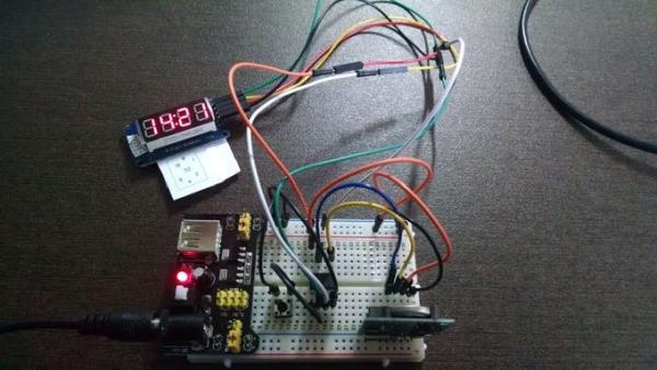
This is my first project using ATtiny85 microcontroller and also including a Real Time Clock (RTC) working with it.
The use of ATtiny85 is a very interesting way to shrink your Arduino projects in a final tiny version.
The Three-Modes Digital Clock includes a version with common decimal clock and also with two versions of binary clock.
One version of binary clock is traditional where each digit of hours and minutes are converted into binary for a LED display of 7 segments.
The last one is my favorite of an unusual version of binary clock where the first digit represents the hour, the second, the minutes and the third the seconds.
An interesting additional feature is about the use of internal memory of RTC that you can save the status of the mode of clock.
This feature is less known and is not applied commonly but give you an extra bonus card for your projects.
Let’s see the project!
You will need for this project:
ATtiny85 microcontroller
Display TM1637 (4 Digits x 7 Segments)
RTC module (DS1307)
Tactile button switch
Breadboard
Wires
Power supply (3V to 5V)
Note:
You can use AA batteries (02x or 03x), for example, or any power supply of 5 Volts at maximum.2 – Schematics & Program
This is my first project using ATtiny85 microcontroller and also including a Real Time Clock (RTC) working with it.
The use of ATtiny85 is a very interesting way to shrink your Arduino projects in a final tiny version.
The Three-Modes Digital Clock includes a version with common decimal clock and also with two versions of binary clock.

One version of binary clock is traditional where each digit of hours and minutes are converted into binary for a LED display of 7 segments.
The last one is my favorite of an unusual version of binary clock where the first digit represents the hour, the second, the minutes and the third the seconds.
An interesting additional feature is about the use of internal memory of RTC that you can save the status of the mode of clock.
This feature is less known and is not applied commonly but give you an extra bonus card for your projects.
Let’s see the project!
You will need for this project:
ATtiny85 microcontroller
Display TM1637 (4 Digits x 7 Segments)
RTC module (DS1307)
Tactile button switch
Breadboard
Wires
Power supply (3V to 5V)
Note:
You can use AA batteries (02x or 03x), for example, or any power supply of 5 Volts at maximum.
2 – Schematics & Program
Schematics
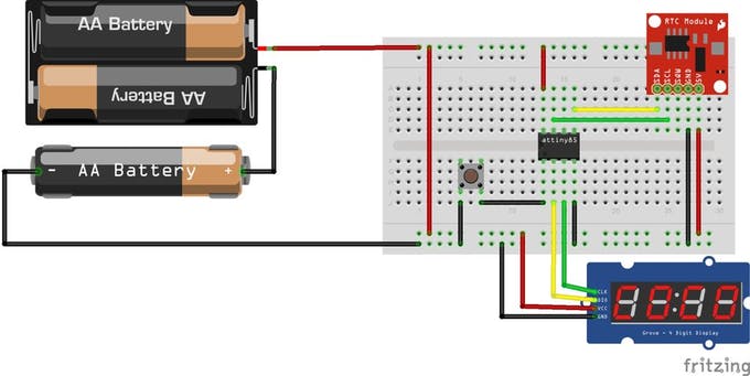
The circuit is shown on attached schematic.
It is very simple, just follow with care the wires connection.
Arduino Program
The program is shown on attached files (INO version).
For more detail: Tri-Mode Digital Clock with ATtiny85 and RTC

