
Summary of TV OSCILLOSCOPE CIRCUIT WITH ATMEGA8515 ATTINY12
This article describes a low-cost, DIY TV oscilloscope project utilizing ATmega8515 and ATtiny12 microcontrollers. It highlights how digital designs simplify construction compared to complex analog versions, offering a sampling frequency of 500 kHz suitable for audio signals. The project includes PCB drawings, schema files, and software to display data on a computer monitor.
Parts used in the TV Oscilloscope Project:
- ATmega8515 microcontroller
- ATtiny12 microcontroller
- Fast AD converter
- FIFO memory
- Control circuit
- PCB drawings
- Schematic files
- Digital solid-source software
Attiny12 ATMEGA8515 a very interesting project based on digital solid-source software and schema files, PCB’s drawings for people working with Atmel series microcontrollers can give different ideas can be useful in different projects analogue… Electronics Projects, TV Oscilloscope Circuit with ATmega8515 ATtiny12″avr project, microcontroller projects, “
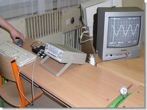
Attiny12 ATMEGA8515 a very interesting project based on digital solid-source software and schema files, PCB’s drawings for people working with Atmel series microcontrollers can give different ideas can be useful in different projects analogue solid
The tv oscilloscope is undoubtedly one of the basic instrumentation in electrical engineering. Oscilloscopes are available in two basic designs – analog and digital. Amateur analog oscilloscope design is relatively complex and expensive, while the construction of the digital oscilloscope is due to the availability of microcontrollers much easier. One of the basic elements of each oscilloscope’s display unit. For analog oscilloscopes can be found with osciloskopickými screens. Modern digital oscilloscopes use different displays, which are often very expensive. Therefore, some structures conceived as modules that can be connected to a computer. Data is then displayed using the software installed on the computer monitor.
TV OSCILLOSCOPE PROJECT

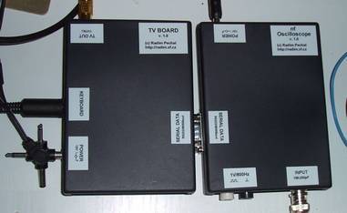
Most digital oscilloscopes consists of a fast AD converter, memory FISO1 and control circuit. This concept is a proven standard, availability-based components allows these units to include single components – a microcontroller. The advantage of this solution is its simplicity and low cost, the disadvantage is the lower sampling frequency oscilloscope. Since the aim was to create a structure oscilloscope, enabling measurement of low frequency frequencies can accept this limitation. The result is an audio oscilloscope that can capture signals with a sampling frequency of 500 kHz.
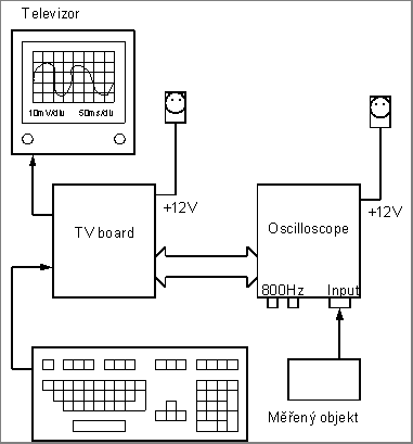
source: https://320volt.com/en/atmega8515-attiny12-ile-tv-osiloskop-devresi/ TV Oscilloscope Circuit with ATmega8515 ATtiny12 schematic code files alternative link: tv-oscilloscope-circuit-with-atmega8515-attiny12.rar alternative link2 alternative link3
Alternative File Download LINK list (in TXT format): LINKS-7993.zip
- What is the main advantage of this digital oscilloscope design?
The design offers simplicity and low cost by using single components like a microcontroller. - Can this project be built using Atmel series microcontrollers?
Yes, the project is based on the Atmel series, specifically the ATmega8515 and ATtiny12. - What is the maximum sampling frequency of this audio oscilloscope?
The oscilloscope can capture signals with a sampling frequency of 500 kHz. - How does this digital design compare to analog oscilloscopes?
Amateur analog design is relatively complex and expensive, while this digital version is easier to construct. - Where is the data displayed in this system?
Data is displayed using software installed on a computer monitor. - Is this oscilloscope suitable for measuring high frequencies?
No, it is designed to measure low frequency frequencies due to its lower sampling frequency limitation. - What files are provided for people working on this project?
The project provides digital solid-source software, schema files, and PCB drawings. - Does the project require an oscilloscope screen?
No, modern digital oscilloscopes often use different displays or connect as modules to computers instead of traditional screens.
