Summary of USB AVR programmer
This article details the construction of a custom USB AVR programmer compatible with STK500v2, designed for laptops lacking LPT ports. The project utilizes an ATMEGA8 microcontroller clocked at 12MHz and includes specific circuitry for voltage level conversion, ESD protection, and USB enumeration. It features configurable settings for programming speed, device emulation mode, and target power supply selection.
Parts used in the USB AVR Programmer:
- Male USB type A connector
- 500mA PTC resettable fuse
- 3.6V fast low current zener diodes
- 68ohm resistors
- 2k2 resistor
- BAV99 double diode
- 4.7uF electrolytic capacitor
- Low current LED diode
- 1k8 resistor
- ATMEGA8 microcontroller
- 12Mhz crystal oscillator
- 22pF capacitors
- 100nF decoupling capacitors
- 10k resistor
- Standard LED diode (optional)
- 74hc126 voltage level converter
- 10pF capacitors
I’ve already had a programmer for Atmel’s AVR microcontrollers, but I couldn’t use it in my lab, because my laptop doesn’t have a LPT port. So I decided to make a new programmer with USB connection. I’ve found an open source programmer AVR doper, and for the basis I took a modified version from the http://www.kreuzholzen.de web page. I designed a new singled sided PCB board, that I was able to make at home. The programmer is compatible with STK500v2.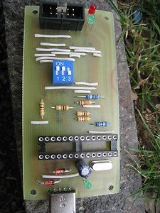 I used a male USB type A connector, so that I can plug the programmer directly in the laptop’s USB port or I can use a USB extension cable. The USB supply is protected with a 500mA PTC resettable fuse on positive lead. To convert the USB data lines from 5V on microcontroller, to the lower voltage used by USB, we use 3.6V zener diodes, that must be fast low current type, and 68ohm resistors. USB D- line is pulled up with 2k2 resistor. This is required for the computer to correctly recognize USB device (for more info you can read the article). For ESD protection we use double diode BAV99 from signal to GND and supply. We also have a 4.7uF electrolytic capacitor on the supply. We can use a LED diode for indication of USB supply. I used a low current LED diode with a 1k8 resistor, if you will use standard diode, you shuld use a lower value resistor.
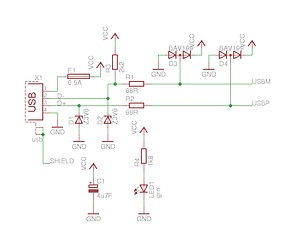
The programmer is controlled with an ATMEGA8 microcontroller. The microcontroller is clocked with 12Mhz crystal with 22pF capacitors. We put the decoupling capacitors (100nF) on microcontroller supply pins and AREF pin. Reset pin is pulled up to 5V with a 10k resistor and protected against interference with 100nF capacitor. On pin PB7 is a LED diode, indicating the programming in progress. The signals are connected to avr as indicated in schematics.
To convert voltage levels from microcontroller from programmer to the programmed microcontroller we use 74hc126. On all signal lines is also a bav99 diode for ESD protection and beads and 10pF capacitors to USB shield against interference.
Three settings are available on avr programmer: 1. Connecting pin SLOW_SCK from microcontroller to GND sets lower programming speed. We can use this setting if our software doesn’t support it. The lower speed of programming is needed when the programmed Atmel microcontroller runs at lower frequency (such as for example 32kHz). 2. Pin ISP_TMOSI pulled to GND with 1k resistor. This settings select the type of USB device the programmer emulates. The recommended setting is the switch in connected position. This sets the type of device to HID, otherwise the device of our programmer will be a serial modem. 3. With this setting we connect the supply of programmer to the supply of programmed avr, so the programmed chip can as well be supplied from the USB port.
For more detail: USB AVR programmer
- Why was this new programmer created?
The author could not use their existing Atmel programmer because their laptop lacks an LPT port. - How is the USB data line voltage converted for the microcontroller?
It uses 3.6V zener diodes and 68ohm resistors to convert from 5V to the lower USB voltage. - What component protects the USB supply?
A 500mA PTC resettable fuse is placed on the positive lead to protect the supply. - How does the computer recognize the USB device?
The USB D- line is pulled up with a 2k2 resistor to ensure correct recognition. - What provides ESD protection in the circuit?
Double diode BAV99 components are used from signal to GND and supply. - What is the function of pin PB7?
An LED diode on pin PB7 indicates when programming is in progress. - How can you set a lower programming speed?
Connecting pin SLOW_SCK from the microcontroller to GND sets the lower speed. - Which setting makes the programmer emulate a HID device?
Pulling pin ISP_TMOSI to GND with a 1k resistor selects the HID device type. - Can the programmed chip be powered by the USB port?
Yes, a specific setting connects the programmer supply to the programmed AVR supply.