
Contents
hide
Summary of How to use fast PWM (Pulse Width Modulation) Mode of AVR microcontroller Timer
This article explains Fast PWM mode on AVR timers, contrasting it with Phase Correct PWM. Fast PWM uses single-slope counting (0 to TOP) producing twice the frequency of Phase Correct PWM. Timer0 is set for Phase Correct PWM (OC0 on PB3) and Timer2 for Fast PWM (OC2 on PD7), both at 50% duty with a 12 MHz clock and prescaler 8, yielding ~2.942 kHz (Phase Correct) and ~5.86 kHz (Fast PWM). Code and circuit connections for ATmega16 are provided, with interrupts updating OCR registers for duty cycle.
Parts used in the Fast PWM with AVR Timer:
- ATmega16 microcontroller
- Crystal oscillator 12 MHz (implied by FREQ definition)
- Programming environment/tools for AVR (avr-gcc, avr-libc)
- Connections to OC0 (PB3) and OC2 (PD7) output pins
- Power supply for ATmega16
- Wires and breadboard or PCB for circuit connections
This article is in continuation of PWM generation using AVR timer. In the previous article, PWM generation using Phase correct PWM mode is described. However, there are some applications like DAC, power regulation and rectification etc. which require high frequency PWM wave. The PWM generation using Fast PWM mode is suitable for such applications. This article focuses on Fast PWM mode of AVR Timer.
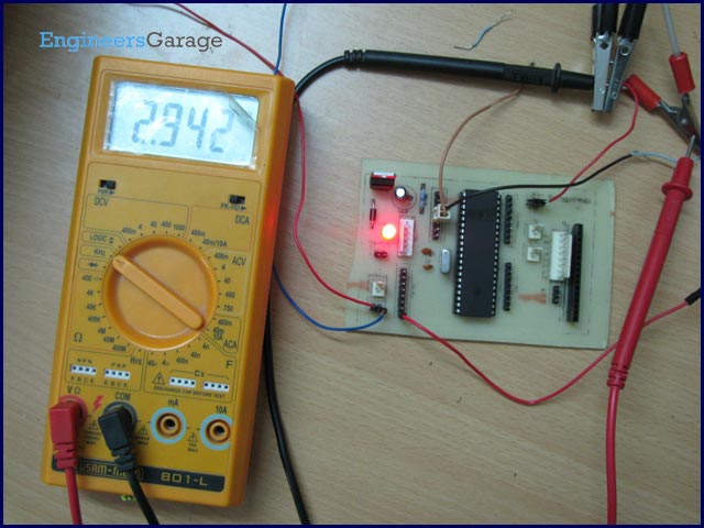
The Fast PWM mode is based on single-slope operation. In single slope operation, the register TCNTn counts from bottom value to maximum value and its value resets to zero. The counting starts again from bottom. The register OCRn compares the value with the TCNTn register constantly. If the timer is configured in non-inverting mode, PWM output pin (OCn) goes low when the value of the above two registers matches. The OCn pin becomes high when the TCNTn register reaches at bottom value. In inverting mode OCn pin behaves opposite to non-inverting mode. For timer 0 fast PWM mode, following table shows the functionality of COM 0[1:0] bits.
Frequency of fast PWM mode signal is twice than Phase Correct PWM mode signal because of its single slope operation.
Output frequency of fast PWM signal = Crystal frequency÷(Prescaler ×256)
Objective: Compare output waveform of Phase correct PWM mode and Fast PWM generated signal.
For this objective Timer 0 is configured in Phase correct PWM and Timer 2 is configured in Fast PWM mode. The Duty cycle of signals is set to 50%.
Circuit description:
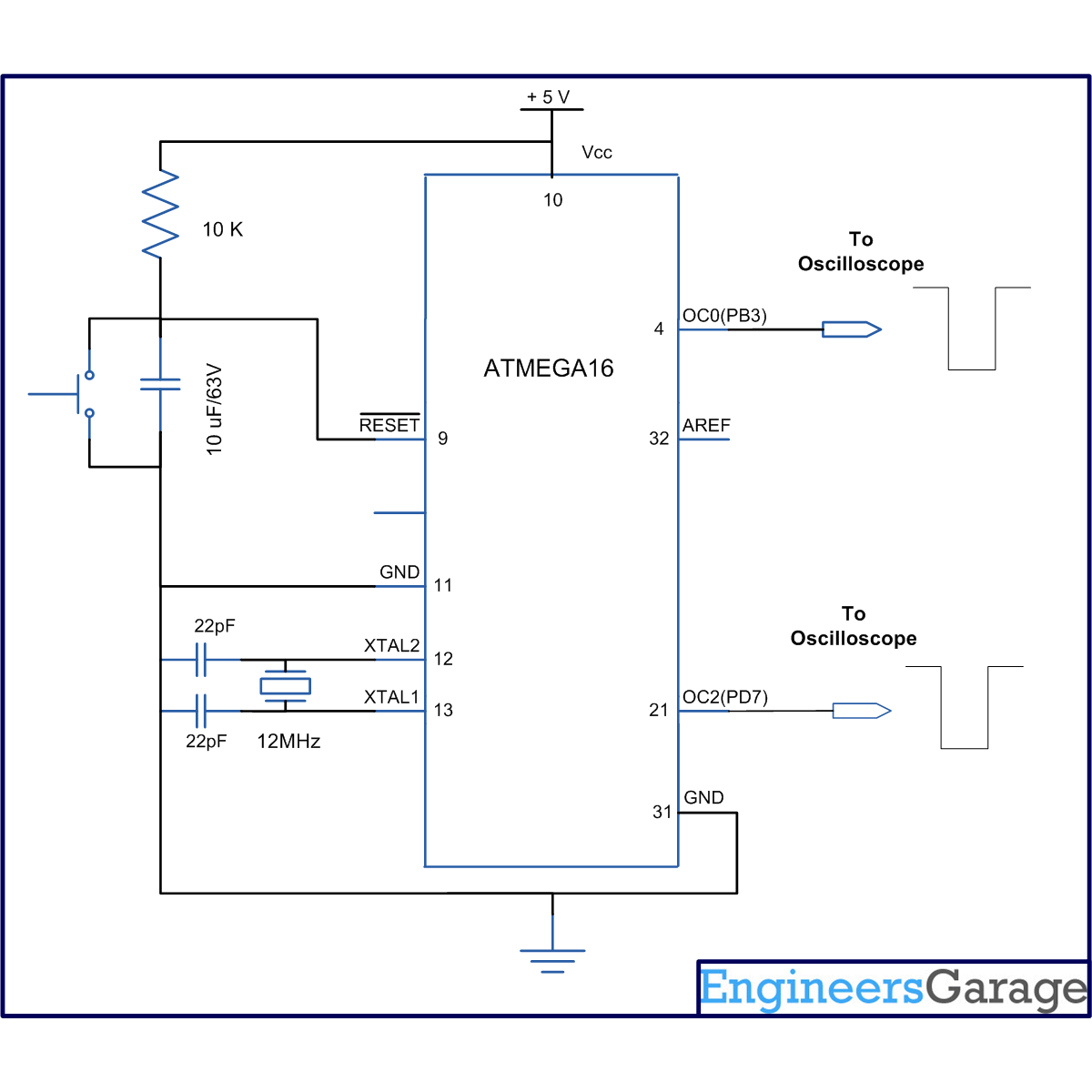
The connection of ATmega16 is shown in circuit diagram. Since, Timer0 and Timer2 are used to generate PWM wave then output will be taken on OC0(PB3) and OC2(PD7) pins respectively.
Programming steps:
The programming steps to configure Phase correct PWM mode is similar as used in previous article. The following steps are written to configure the Timer2 for Fast PWM mode:
1. Select Fast PWM mode by programming WGM2 [1:0] bit.
2. Program COM2[1:0] and select inverting or non-inverting mode.
3. Set OC2 pin as output pin.
4. Set OCIE2 bit of TIMSK register.
5. Enable global interrupt by “sei()” command.
Output waves:
Phase correct PWM wave frequency by formula:
Output frequency= Crystal frequency÷(Prescaler ×510)
= 12000000 ÷ (8×510)
= 2941.17 Hz = 2.941KHz
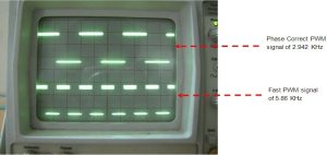
Practically, the output wave form has frequency of 2.942 KHz with 50% duty cycle.
Fast PWM frequency by formula:
Output frequency= Crystal frequency ÷ (Prescaler ×256)
= 12000000 ÷ (8×256)
= 5859.375 Hz = 5.859 KHz
Practically, the output wave has frequency of 5.86 KHz with 50% duty cycle.
This experiment proves that Fast PWM wave has twice the frequency of Phase Correct PWM wave.
Project Source Code
###
// Program to use fast PWM (Pulse Width Modulation) Mode of AVR microcontroller Timer
#include<avr/io.h>
#include<util/delay.h>
#include<avr/interrupt.h>
#define FREQ 12000000
#define duty_cycle 50 // duty cycle require
#define prescaler 8
#define OCR_value ((duty_cycle*256)/100) //OCR value calculation
void t0_pwm_init(void);
void t2_fastpwm_init(void);
int main()
{
t0_pwm_init();
t2_fastpwm_init();
sei();
while(1);
}
void t0_pwm_init() // initialization for Phase Correct PWM signal using timer 0
{
// WGM0[1:0]= 01, for Phase Correct PWM mode
// COM0[1:0]= 10, to select non inveting mode
// CS0[2:0] =010. for prescaler=8
TCCR0=(1<<WGM00)|(2<<COM00)|(2<<CS00);
DDRB|=(1<<PB3); // selcet OC0 as output pin
TIMSK|=(1<<OCIE0); //enable Output compare interrupt
}
void t2_fastpwm_init() // initialization for Phase Correct PWM signal using timer 2
{
// WGM2[1:0]= 11, for Fast PWM mode
// COM2[1:0]= 10, to select non inveting mode
// CS2[2:0] =010. for prescaler=8
TCCR2=(1<<WGM20)|(1<<WGM21)|(2<<COM20)|(2<<CS20);
DDRD|=(1<<PD7); // selcet OC2 as output pin
TIMSK|=(1<<OCIE2); //enable Output compare interrupt
}
ISR(TIMER0_COMP_vect) // interrupt subroutine
{
OCR0=OCR_value; // put OCR value
}
ISR(TIMER2_COMP_vect) // interrupt subroutine
{
OCR2=OCR_value; // put OCR value
}
###
Circuit Diagrams
| Circuit-Diagram-of-How-to-use-fast-PWM-Pulse-Width-Modulation-Mode-of-AVR-microcontroller-Time |
- What is the main difference between Fast PWM and Phase Correct PWM?
Fast PWM uses single-slope counting (0 to TOP) while Phase Correct PWM uses dual-slope counting, giving Fast PWM twice the output frequency. - How is the Fast PWM frequency calculated?
Output frequency = Crystal frequency ÷ (Prescaler × 256) as stated in the article. - What frequency do you get with a 12 MHz crystal and prescaler 8 in Fast PWM?
The article calculates 12000000 ÷ (8 × 256) = 5859.375 Hz, practically 5.86 KHz. - What frequency does Phase Correct PWM produce with the same clock and prescaler?
Output frequency = 12000000 ÷ (8 × 510) = 2941.17 Hz, practically 2.942 KHz. - Which pins are used for PWM outputs in this project?
OC0 on PB3 for Timer0 and OC2 on PD7 for Timer2. - How is a 50% duty cycle achieved in the provided code?
OCR value is set using OCR_value macro defined as (duty_cycle × 256) ÷ 100 with duty_cycle = 50. - What timer settings are used to enable Fast PWM on Timer2?
WGM20 and WGM21 set to 1 for Fast PWM, COM20/21 set for non-inverting, and CS2 set for prescaler 8, as shown in t2_fastpwm_init. - Are interrupts used to update the OCR registers in the example?
Yes, Output Compare interrupts OCIE0 and OCIE2 are enabled and ISR routines assign OCR0 and OCR2 respectively.
