Summary of Use an LM317 as 0 to 3V adjustable regulator
### Summary This article addresses the limitation of the LM317 adjustable regulator, which cannot output voltages below its 1.25V internal reference. It critiques using two diodes for biasing due to temperature instability and high costs of dedicated ICs like the LM185 or AD589. The proposed solution involves implementing a simple, temperature-stabilized constant-current source using specific components to generate the necessary -1.25V bias, enabling the LM317 to function as a 0 to 3V adjustable regulator.
Parts used in the LM317 Adjustable Regulator Project:
- Fairchild Semiconductor's LM317
- Two 1N4001 diodes (for comparison)
- Fairchild Semiconductor LM185 (for comparison)
- Analog Devices AD589 (for comparison)
- D1 Diode
- Q1 Transistor
- Resistor R5
- Resistor R6
- Resistor R3
Most engineers know that they can use an inexpensive, three-terminal adjustable regulator, such as Fairchild Semiconductor’s LM317, as an adjustable regulator to only some necessary value of voltage, such as 36 or 3V. This value cannot be less than 1.25V without employing other approaches, however. The devices’ inner reference voltage is 1.25V, and their output voltage accordingly cannot be less than this value without potential bias (Reference 1).
One way to solve this problem is to use a reference-voltage source based on two diodes (Reference 2). Although this approach is suitable for a 1.2 to 15V or higher-voltage regulator, it is not appropriate for an extra-low-voltage fixed- or adjustable-voltage regulator. The two 1N4001 diodes it employs do not provide the needed potential bias of 1.2V, and they have additional temperature instability of approximately 2.5 mV/K (Reference 3). Hence, additional temperature drifting of the output voltage is approximately 100 mV; it is more than 6% for a 1.5V output voltage and 10% for a 1V output voltage if you adjust the temperature to 20°C—a typical indoor situation. You can solve these problems by using a Fairchild Semiconductor LM185 or an Analog Devices AD589 adjustable-voltage-reference IC. These devices are expensive, however, and, in this case, they require not only additional zero adjustment but also matching. These adjustments at their reference voltages are 1.215 to 1.255V and 1.2 to 1.25V for the LM185 and AD589, respectively. Note that the reference voltage of the LM317 is 1.2 to 1.3V.
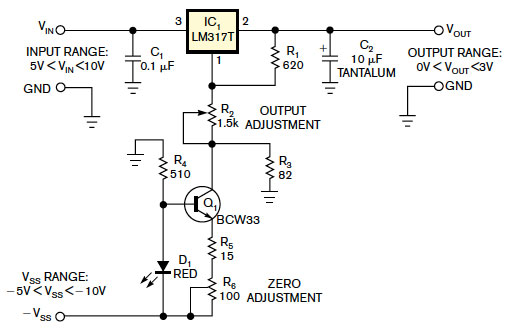
mplement the necessary potential bias using a simple temperature-stabilized constant-current source (Reference 4). You calculate this current source using the following equation: I=(VF–VEBO)/(R5+R6), where VF is D1’s forward voltage of approximately 2V and VEBO is Q1’s emitter-base voltage of approximately 0.68V. The current is approximately 1.32/(R5+R6). The constant-current source creates a bias voltage of approximately –1.25V on resistor R3.
For more detail: Use an LM317 as 0 to 3V adjustable regulator
- What is the minimum output voltage limit of an LM317 without modification?
The output voltage cannot be less than 1.25V without employing other approaches. - Can two 1N4001 diodes provide the needed potential bias for low-voltage regulation?
No, they do not provide the needed potential bias of 1.2V and suffer from additional temperature instability. - How much temperature drifting occurs with the two-diode approach at a 1.5V output?
The additional temperature drifting is more than 6% for a 1.5V output voltage. - Why are the LM185 and AD589 considered problematic for this specific application?
These devices are expensive and require additional zero adjustment and matching. - What equation calculates the current for the proposed constant-current source?
The current is calculated using the equation I=(VF–VEBO)/(R5+R6). - What approximate bias voltage does the constant-current source create on resistor R3?
The source creates a bias voltage of approximately –1.25V on resistor R3.