Summary of Using the AVRISP Programmer
The article explains how to use the AVRISP mkII programmer with an ATmega16 microcontroller. It details hardware setup, including connecting a 3x2 pin header to a breadboard and wiring ISP signals (MISO, MOSI, SCK, RESET) alongside power lines. The guide covers software configuration in AVR Studio to verify communication via signature reading before programming the device's flash memory.
Parts used in the AVRISP Programmer Project:
- AVRISP mkII programmer
- JTAGICE (for comparison)
- ATmega16 microcontroller
- 3x2 pin header
- Breadboard
- Pliers
- USB cable
- LEDs for PORTB
Introduction
The AVRISP looks just like the JTAGICE, except it’s a bit smaller and it has a 6-pin connector on the end of the cable instead of the 10-pin connector on the JTAGICE.

The AVRISP programmer does not have the advanced debugging features of the JTAGICE, but it still allows you to load your program onto the ATmega16. You should try using the AVRISP first, and then if you find that you can’t debug your program without stepping through and setting breakpoints, switch to the JTAGICE.
The setup for the AVRISP is different than the JTAGICE, but you can have your breadboard set up with headers to connect both devices so that it’s easy to switch between the two.
Connecting the AVRISP to your board
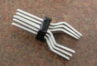
Obtain a 3×2 pin header. I’ve placed a bunch of these in the supply cabinet with the resistors. Use your pliers to bend the longer set of pins so that the header can be plugged in across one of the gaps in your breadboard.
Plug the header into your breadboard. You probably want to locate it near pin 1 on the ATmega16 to keep your wires short. The following diagram shows the pinout for the ISP (In-System Programming) connector:
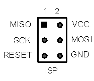
Wire VCC and GND to VCC and GND on your board, and connect MISO, MOSI, SCK, and RESET to the corresponding pins on your ATmega16 (see the AVR datasheet for the pins on the ATmega16). It’s okay that you will be sharing some wires with the LEDs you have connected to PORTB. Both the programmer and LEDs will work properly with everything connected at the same time. The result should look something like this:
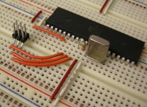
Plug the 6-pin connector on the end of the AVRISP’s cable into the 6-pin header on your board. The red wire indicates the side of the connector with pin 1. Plug the USB cable into your PC, and install the drivers when Windows prompts you. Once the drivers are loaded, the LED on the AVRISP should turn green to indicate that it detects the target voltage on your board.
First-Time Setup
The first time you use the AVRISP with your board, you should follow these setup instructions. For subsequent uses, you can skip ahead to the Programming section.
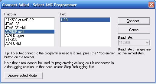
Open a project in AVR Studio, and click the  button in the toolbar to make sure your program is compiled and up-to-date. Select the AVRISP mkII as the platform and USB as the port, then click the Connect button:
From the window that appears, select the Main tab. Make sure that the device type is set to ATmega16, and click the Read Signature button. The chip signature for the ATmega16 (0x1E 0x94 0x03) should appear in the window. This verifies that the programmer can communicate with the ATmega16.
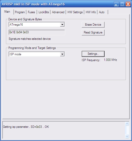
If reading the signature fails, verify that there is a green light on the AVRISP (if not, it is incorrectly wired to VCC and GND, or your board is not plugged in to power) and that your wiring of the MISO, MOSI, SCK, and RESET lines is correct. If the AVRISP still will not read the device signature, it’s possible that ISP programming is disabled in your ATmega16 (we have a few chips still set this way.) You can exchange your ATmega16 for one that’s properly programmed with a TA.
Next, check to make sure that the ISP frequency is set to 1.000 MHz. If it is not, click the Settings button, select 1.000 MHz from the menu that appears, and click the Write button.
You’re now ready to program your ATmega16 using the AVRISP mkII.
Programming with the AVRISP mkII
To load your program onto your processor, first click the build button in the toolbar (Don’t use the “build and run” button, since no debugging platform is connected.) Then, click the AVR button and go to the Program tab. Under the Flash section, make sure the hex file for your project is selected, and then click the Program button.
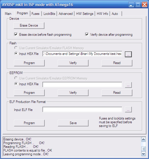
The program will be loaded onto your ATmega16 and should start running automatically, though it never hurts to hit the reset button and make sure that your program starts properly from the beginning.
Source: Using the AVRISP Programmer
- How does the AVRISP differ from the JTAGICE?
The AVRISP is smaller, has a 6-pin connector instead of 10, and lacks advanced debugging features like stepping through code or setting breakpoints. - Can I use both the AVRISP and JTAGICE on the same breadboard?
Yes, you can set up headers on your breadboard to easily switch between the two devices. - What components are needed to connect the AVRISP to the board?
You need a 3x2 pin header, pliers to bend the pins, and wires to connect VCC, GND, MISO, MOSI, SCK, and RESET. - Does sharing wires with LEDs affect the programmer?
No, both the programmer and LEDs will work properly when sharing wires connected to PORTB. - What indicates that the AVRISP detects target voltage?
The LED on the AVRISP should turn green after drivers are loaded and the device is connected. - What steps verify successful setup in AVR Studio?
Select the Main tab, ensure the device is ATmega16, and click Read Signature to confirm the chip signature appears. - What frequency should be set for ISP programming?
The ISP frequency must be set to 1.000 MHz using the Settings button. - Which build button should be used before programming?
Use the standard build button in the toolbar rather than the build and run button since no debugging platform is connected.