Summary of Water Tank Level Alarm & Pump Cutoff (ESP8266 & MicroPython)
This article details a DIY water tank level monitoring and pump cutoff system using an ESP8266 microcontroller. The project addresses low water pressure issues by installing induction sensors to detect warning (60%) and alarm (25%) levels. When the alarm threshold is reached, the system cuts power to the water pumps via a relay to prevent dry running, while providing visual LED indicators and audible buzzer alerts. It includes a manual override switch to restore pump power if needed and is housed in a wall-mounted box for safety with AC mains.
Parts used in the Water Tank Level Alarm & Pump Cutoff:
- Wemos D1 mini (ESP8266) Microcontroller
- Wemos D1 mini relay shield
- Resistors: 220 ohm, 10K ohm, and 330 ohm
- PC817 Optocoupler IC (DIP 4)
- Piezoelectric buzzer
- 220VAC to +5V 600ma switching power supply
- JST XH 4pin and 2 pin male board sockets
- SPST Switch for DC power
- LEDs: Green, Orange, and Red
- 2 terminal screw block AC Connector
- 5cm x 7cm perfboard
- Wall mounted double wall socket box
- Mini AC 3 pin outlet modules
- AC switch plug module
- AC Lead + plug
- Cable clamps or ties
INTRODUCTION
Our new home has an interior 700L water tank with an electric pump supplying pressure to the house.
Unfortunately, at times of peak demand, the external water supply pressure can drop so that the water tank is not refilling. This usually happens on a Sunday when we are in the middle of weekly laundry, car washing etc.
With experience we found that this usually rectifies itself overnight. But, that doesn’t help when you have no water for the rest of the day !
As the saying goes: “Necessity breeds Invention”. I went looking for a suitable water level alarm to at least let me know when the water level is dropping dangerously low so we can take it easy.
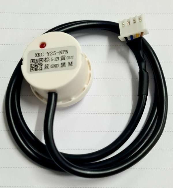
Found some induction water sensors (XKC-Y25-NPN 5-12V) that can be placed on the outside of the tank.
I also found a controller (C350-3P) unit that had three of these sensors and connections for hardwired power connections. However, as I had been playing around with microcontrollers I was looking for a smarter solution with some possible future upgrades including linking to my smart home. So after playing around a bit I came up with this design.
Please take it easy on me as this is my first “Instructable” and as usual I am sure there are many and varied ways of doing this. I was impressed with the Ultrasonic Sensor Water Level monitor but I decided to go ahead with this version anyway.
I liked it because the sensors were inexpensive, I already had some experience with ESP8266 and Micropython and let’s face it, these sorts of builds with a decent purpose are fun to do !
Supplies:
Parts needed:
Qty Type Description
- 1 x – MCU – Wemos D1 mini (ESP8266) Microcontroller
- 1 x – Relay – Wemos D1 mini relay shield
- 3 x – 220 ohm – Resistor: LED Current Limiting (Status, Alarm, Warning) for +3.3V
- 2 x – 10K ohm – Resistor: GPIO IN Pull Down (D6, D7 for sensors)
- 2 x – 330 ohm – Resistor: LED Current Limiting (2 x optocoupler) for +5V
- 2 x – Optocoupler – PC817 IC (DIP 4)
- Convert NPN sinking output to sourcing Input to GPIO pins at GPIO voltage +3.3V
- 1 x – Buzzer – Piezoelectric buzzer works ok with +3.3V GPIO output.
- 1 x – PSU – 220VAC to +5V 600ma block switching power supply
- 2 x – JST XH 4pin – 4 pin male board socket for sensors (Sensors come standard with this plug.)
- 4 x – JST XH 2 pin – 3 x 2 pin male board socket for LED (Status, Warning, Alarm)
- 1 x 2 pin male board socket for DC switch
- 1 x – SPST Switch for the DC power switch +5V to the MCU.
- 3 x – LED – 1 x green, 1 x orange, 1 x red.
- 1 x – AC Connector – 2 terminal screw block for AC IN
- 1 x – Perfboard – 5cm x 7cm (18 x 24 holes) 2 sided perfboard
- 1 x – Wall Box – Wall mounted double wall socket box
- 2 x – 3 pin outlet module – Mini AC 3 pin socket for mounting in wall box
- 1 x – AC Switch module – AC switch plug module for wall box
- 1 x – AC Lead + plug – Lead to connect wall box to AC Mains
- 2 x – Cable clamp – I used cable ties and adhesive blocks to secure AC lead and sensor leads inside the box.
Step 1: Project Description
Purpose:
1. To monitor and display 2 water tank levels (Warning, Alarm)
2. If water level drops below the low level (Alarm), cut power to water pumps to prevent the tank from getting completely empty.
3. Have an override function to enable water pump power when tank level is below Alarm level.
Sensors:
Uses 2 x induction water sensors (XKC-Y25-NPN 5-12V) on the home water tank.
1. Warning Sensor placed at 60% level
2. Alarm sensor placed at 25% level
These sensors are configurable and these are set so that the signal at the GPIO sensor Pin is LOW when water is detected and HIGH for no water detected.
MCU:
1. Wemos D1 Mini (ESP8266)
Language:
1. Micropython (version 1.14)
Indicators:
1. Status LED (Green)
lights up solid when code running
2. Warning LED (Orange)
blinks 1 per second when warning sensor triggered and stays flashing until water level is back above 60%
3. Alarm LED (Red)
blinks 2 times per second when alarm level reached and stays flashing until water level is back above 25%
4. Buzzer.
Activated at both Warning (30 seconds) and Alarm (60 seconds) levels.
Power:
Dual AC Mains sockets for water pumps:
i) House Water Pump
ii) RO Filter pump
Relay connected to water pump mains supply. Uses the Normally Closed (NC) connection so that if controller power is OFF the power is ON to the pumps. When the Alarm level is triggered the relay is ENABLED which cuts power to the AC sockets and water pumps.
MCU Power:
1. AC220V to DC+5V Switching Power Supply (600mA)
Switches:
1. AC Mains Switch Cuts ALL power to controller AND AC sockets (pumps)
2. MCU Power Switch & Alarm Override
Connected to the output of the +5V power supply going to the MCU.
This halts the MCU, all LEDs shutoff and the relay is DISABLED which turns the power back ON to the pumps.
This allows a manual override so the water can be turned back on when the level is still below 25%
Note: Power is still ENABLED to the Water Level Sensors which both have external LEDs.
Step 2: Schematic
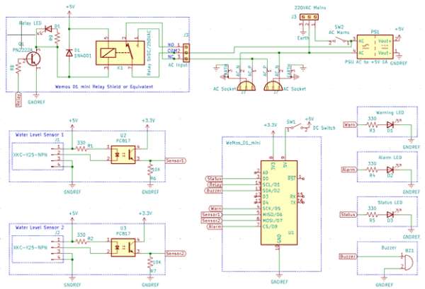
The critical design elements are:
- Be electrically ‘safe’ as it is AC220V. So use a conventional double wall mounted socket box to house the controller.
- Primary control using an ESP8266 MCU
- All power derived from AC.
- Use the induction sensors to detect water level at 2 pre determined levels. Most of the rest of the circuitry is about linking these sensors to the MCU. The ESP8266 GPIO pins are at +3.3V max. Also the NPN sensor is a SINK so need the optocouplers to invert the signal and voltage level.
Sensors: XKC-Y25-NPN
1. This is a Sinking output sensor. When the internal transistor is Enabled the output lead is connected to Ground.
2. Mode lead determines if Output active is linked to Water detected or no water detected.
Important: For an NPN sensor the Output is ALWAYS a SINK.
3. VCC range +5V – +12V. +5V used here.
4. Wiring: 1-VCC-Brown, 2-Output-Yellow, 3-GND-Blue, 4-Mode-Black
5. Operating Mode: Mode connected to GND.
i) When water detected (Induction positive) then the Output lead is OPEN and the
GPIO sensor Pin is LOW.
ii) No water detected (No induction) then the Output lead is CLOSED to GND and the
GPIO sensor Pin is HIGH.
6. For alternative Mode connect the Mode lead to VCC. This swaps the Output operation.
Induction positive = Output lead CLOSED and connected to GND
No Induction = Output lead OPEN
Note: Not used in this circuit.
Step 3: Circuit Board Design
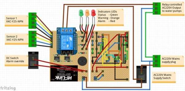
As you can see I chose a perfboard rather than PCB. Mainly because I am not setup to create a homemade PCB yet. Also this curcuit is relatively simple and even with a perfboard can still fit in the double outlet wall box.
Step 4: Circuit Board Assembled
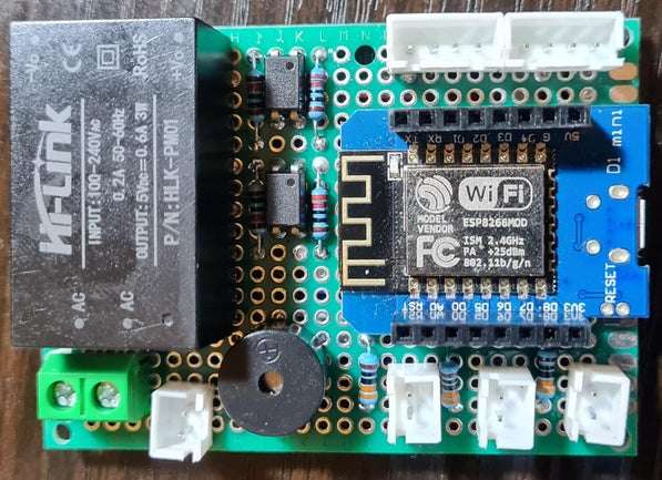
Top layout looks pretty good.
I’m sure the bottom could be vastly improved but it works well enough.
I know that I did not make use of the top layer for any electrical connections. However, I chose a 2-layer board because it is still very cheap and a lot stronger. No chance of popping pads off the one layer board if you handle it wrong.
Step 5: MicroPython
Here are the two micropython files for the Wemos MCU.
For this phase 1 deployment I am using a simple BOOT.PY with no networking or Webrepl.
Yes I realise any code changes will need disassembly for the unit to get at the USB port.
A future version may link this to my smarthome as the Wemos d1 has WiFi capability.
The water tank level py file will become the ‘main.py’ code on the MCU.
Step 6: Assembly
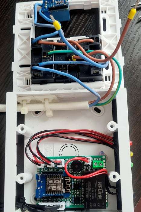
Please note that I live in Thailand. This means that the AC outlets are NOT polarised for Live & Neutral.
This is why my AC wiring on the back of these outlets are not completely correct. Ideally the Live will connect only to the main AC switch and from there will connect to the AC sockets Live terminal, Relay and Power Supply.
If you make this is a country where Live is specified please make sure to properly route it to the AC socket’s Live terminals.
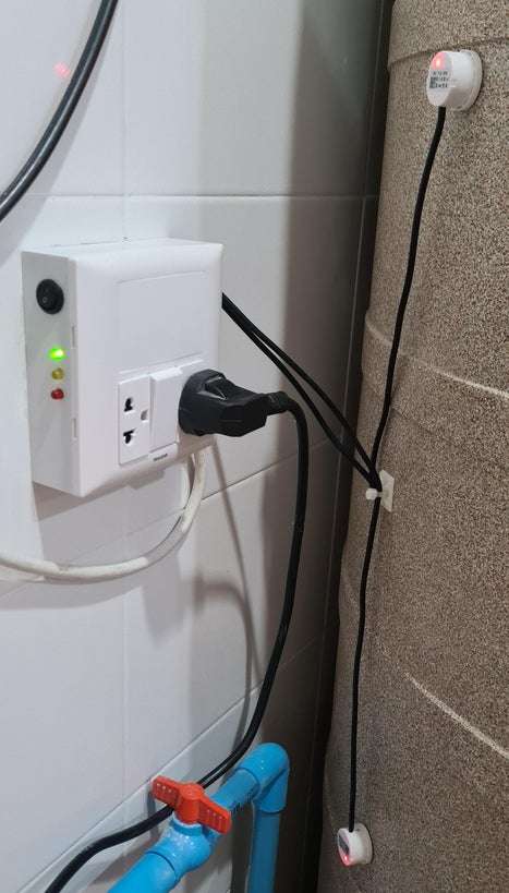
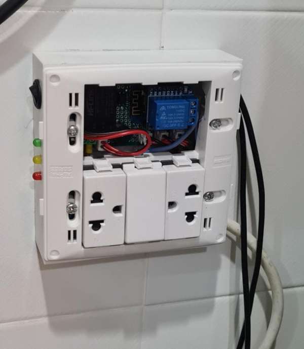
Step 7: Installation
Step 8: Operation
Power On
- Plug water pump(s) into the controller.
- Turn DC switch OFF (No power to microcontroller (MCU)
- Plug controller to AC Mains
- Turn ON controller Mains switch (between the sockets)
- AC power is ON to water pumps and the +5V power supply and sensors.
- Sensors both get +5V so they will turn on. They each have their own indicator Red LED,
- Wait for sensors to power up and they will indicate (Red LED ON) if there is water at their level. Which should be most of the time.
- Turn ON the DC switch to enable the microcontroller
Normal Operation
- Once main.py starts the green Status LED will flash 2 times and they stay on solid.
- The code refreshes the alarm settings on power up so if both sensors have water then the Warning (Orange) and Alarm (Red) LED’s will be OFF.
- This should also mean that both Sensors on the tank show a Red LED ON.
Warning Level activated
- When the water level drops below the top sensor the buzzer will sound and the Warning LED (orange) will start flashing 1 time per second.
- Power to the pumps is NOT affected.
- This is a Warning ONLY
Alarm level activated
- When the water also drops below the lower Alarm level sensor (25%):
- The buzzer will sound for a time
- The Warning LED will be turned OFF
- The Alarm LED (red) will be turned ON and flash at 3 times per second
- The relay will be activated and power turned OFF for the water pumps.
Alarm Deactivation
- When water level returns above the Alarm sensor (25%) the controller will automatically:
- Disable the Alarm LED
- Disable the relay and turn power ON to the pumps.
- Enable the Warning level alarm function
Override
- To override the controller and turn power back ON to the pumps even below the 25% level simply turn OFF the DC switch. The effects are:
- No power to the MCU
- Relay is disabled so power is turn ON to the pumps
- All controller indicator LEDs are turned OFF
- To re-enable the controller, turn the DC switch back ON. The controller will refresh itself based on current sensor inputs and reset any alarms if needed.
Source: Water Tank Level Alarm & Pump Cutoff (ESP8266 & MicroPython)
- How does the system handle low water levels?
The system uses two induction sensors set at 60% for warnings and 25% for alarms to trigger LEDs and a buzzer. - Can I manually override the pump cutoff?
Yes, turning off the DC switch disables the MCU and relay, restoring power to the pumps even below the 25% level. - What happens when the alarm level is reached?
The relay activates to cut power to the water pumps, the red LED flashes three times per second, and the buzzer sounds. - Does the system automatically restart the pumps?
Yes, once the water level returns above the 25% sensor, the controller disables the alarm and re-enables power to the pumps. - Why are optocouplers used in this circuit?
Optocouplers convert the NPN sinking output from the sensors to a sourcing input compatible with the +3.3V GPIO pins of the MCU. - What programming language is used for the microcontroller?
The project utilizes Micropython version 1.14 on the Wemos D1 Mini. - How are the sensors wired for detection?
The sensors are configured so the GPIO pin reads LOW when water is detected and HIGH when no water is present. - Is the device safe to connect to AC mains?
The design uses a double wall-mounted socket box and relies on standard wiring practices to ensure electrical safety.