Summary of Weeks 11-12: AVR USB Devices and Programming
This article details the process of designing and programming a custom USB device using an ATmega16U2 microcontroller. The author explores hardware versus software USB implementation, selects the ATmega chip for its hardware support, and designs a circuit using a 16MHz crystal and impedance matching resistors. The project involves creating a PCB schematic in Eagle, milling the board with specific end mills to accommodate tight pin spacing, and troubleshooting issues like trace resolution and copper remnants before testing connectivity.
Parts used in the Custom USB Device:
- ATmega16U2 (or ATmega32U2) microcontroller
- 16MHz quartz crystal (HC-49 surface mount package)
- USB A connector
- RGB LED
- Three switches
- Power LED
- Impedance matching resistors
- Capacitors paired with the crystal
One of the relatively unexplored topics in this week’s lecture was USB, the ubiquitous protocol that allows computers to communicate with peripheral devices (containing microcontrollers). Creating a USB device allows any computer to talk to it without the specialized software and hardware we’ve been using so far. For these two weeks, I decided to understand the requirements to create USB-compatible device circuits and write the necessary software for a computer to talk to them.
This is an epically long post about creating a USB device from scratch and programming it.
Hardware or Software USB?
Making a USB device requires programming a microcontroller that can talk to a computer with the USB protocol. So far in the class, we’ve been writing microcontroller code that communicates with various protocols. It’s also possible to do this with USB, and the V-USB library implements this. However, having the microcontroller emulate USB in software has several drawbacks, including that it’s slow, and that the microcontroller will need to devote some amount of time to USB communication.
On the other hand, microcontrollers with hardware USB support offload the necessary computations to dedicated circuitry. In Atmel’s AVR line, Mega and XMega devices with the U suffix have hardware USB support. In order to write microcontroller code to interact with the USB hardware, there are helper libraries such as Atmel’s USB stack and LUFA. I’ll be exploring LUFA as it’s open source, is well documented, and has many examples.
Circuit Design
In the class inventory, we have a couple of devices with hardware USB support: the ATmega16U2 and the ATXMEGA16A4U. Because LUFA support for the XMEGA AVRs is currently not well-supported, I’ve opted to go with the ATmega chip.
Given that we’ll use the ATMega16U2, what’s next? Well, it turns out that there aren’t many examples of USB device circuits for microcontrollers floating around online. Even the datasheet isn’t very specific about examples of application circuits. However, after a long search, I was happy to discover that the Arduino Uno revision 3 uses an ATMega16U2 chip as a USB to serial converter for the actual ATmega328p being programmed. Its schematic was very helpful as an example to build a basic circuit.
From various datasheets and other examples, I have found several things to be aware of when designing these circuits:
- In order to use Full-speed (12 Mbit/s) USB, the microcontroller needs to be able to generate a precize 48 MHz clock with a deviation of no more than 0.25%. Since resonators have 0.5% tolerance, This means only quartz crystals can be used, and moreover they need to evenly divide into this frequency in order for a phase-locked loop to generate this clock. For the ATMega16U2, this will require a 8MHz or 16MHz crystal – no substitutes.
- Different quartz crystals at the same frequency are not interchangeable; they are specced at a fixed load capacitance that must be matched by the circuit for the specified accuracy. If this capacitance is far off, the crystal can be slower or faster than intended.
- The USB signaling pins require resistors for impedance matching to optimize signal quality. The datasheet shows some unspecified resistors here, and I discovered the reason by asking this Electronics StackExchange question.
After the due diligence on the circuit engineering, I was finally ready to design the schematic. Because I was using some non-standard parts here, I found the Ladyada and Sparkfun Eagle libraries to be useful. In the circuit below, I’m using a 16MHz crystal in a HC-49 surface mount package, an ATmega32U2 – pin compatible with the ATmega16U2, and a USB A connector directly on the PCB.
The Eagle libraries also include supply parts which make it easier to create VCC and GND connections by dropping parts instead of naming nets. I strongly recommend this as a workflow! Note also the impedance matching signaling resistors, and the capacitors paired with the crystal, the values of which I borrowed from the Uno rev. 3 because of its similar configuration.
A power LED automatically lights up when the board is powered – a nice feature to have. The RGB LED in the circuit is attached to hardware PWM pins, so that it can be controlled with full color by setting the corresponding PWM rates.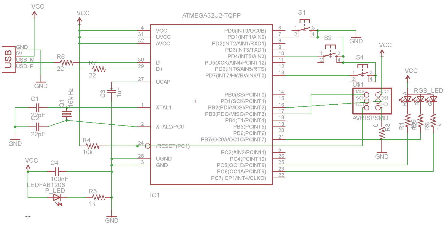
The mega16U2 comes in a TQFP32 package, similar to the mega328P. Compared with the pins on the tiny44 and tiny45, they are much closer together and smaller. In order to mill traces for them, one will either need to use a 10 mil end mill, or edit the pads to allow for more space with them. Given the overall stress caused to the class from 10 mil end mills, I decided to edit the pads to so that I could mill the board with the normal 1/64” end mill. Note that this makes the pads narrower than the pins, so soldering will be harder.
To change the pad size, you can just open the library in Eagle and use the following menu. Here, I’ve changed the TQFP32 package’s pads from 0.16 x 0.05 to 0.14 x 0.06 – slightly thinner, but longer. In routing the board, I used 0.14” routes when connecting to all of the pads, and widened them to the 0.16” routes as soon as they left the vicinity of the microcontroller.
This is the board, all laid out. My original design had many more LEDs and switches, but it turned out I had bit off much more than I could chew – or lay out on a single-sided board. I removed many of the extra parts, and settled on three switches and one RGB LED. After many hours of routing, I came up with this compact, symmetric design using the integrated USB connector. It’s a pity that the mega16U2 doesn’t have any ADC hardware, or I would have added several sensors to read later via USB.
Here’s the result of milling the board. Note that there are some traces pulling off in the center of the board, which is less than ideal. This board was exported at 1200 DPI, but that still wasn’t enough for the very fine detail in the middle – the microcontroller pads and traces should only be slightly narrower than normal, but they appear to be significantly narrower in some spots. If I were to do this again, I’d export at an even higher resolution.
Although I used 6 offset paths instead of the normal 4, there are still copper traces around the edge of the board. This is a problem around the USB connector, where we don’t want to be shorting random pins to each other. I shaved these unwanted copper parts off with an X-acto knife.
I tested the board out in a USB socket and read the pin voltages, just to make sure the connector will work: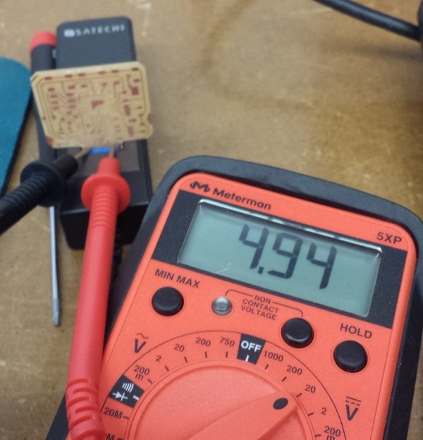
For more detail: Weeks 11-12: AVR USB Devices and Programming
- Why did the author choose hardware USB over software USB?
Hardware USB offloads computations to dedicated circuitry, whereas software emulation is slow and requires significant microcontroller time. - Which library was selected for interacting with the USB hardware?
The author chose LUFA because it is open source, well documented, and has many examples. - What type of clock source is required for Full-speed USB operation?
A precise 48 MHz clock is needed, which requires a quartz crystal rather than a resonator due to tolerance requirements. - Why were the TQFP32 package pads edited in the Eagle design?
The pads were modified to allow milling with a normal 1/64 inch end mill instead of a difficult 10 mil end mill. - What specific crystal frequency is compatible with the ATMega16U2?
An 8MHz or 16MHz crystal is required; no substitutes are acceptable for this chip. - How was the issue of unwanted copper traces around the board edge resolved?
The author shaved off the extra copper parts around the USB connector using an X-acto knife. - What limitation prevented the addition of sensors to the final design?
The mega16U2 does not have any ADC hardware, preventing the reading of analog sensors via USB.