- Who does not want to have stunning lamp which can display animations and sync with other lamps in the house?
Right, nobody.
That’s why I made a custom RGB lamp. The lamp consists of 256 individually addressable LED’s and all of the LED’s can be controlled via a smartphone app. Additionally, you can build multiple of them and make a Nanoleaf like lamp (but this is actually better).
Supplies:
- Square lamp shade
- 16×16 LED matrix
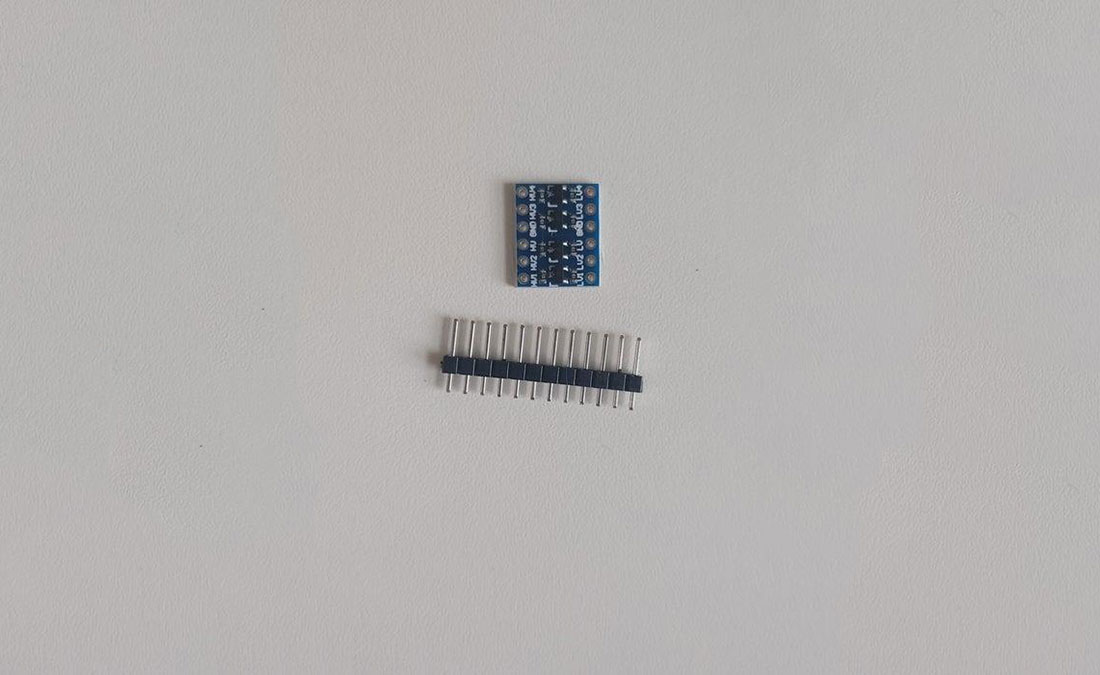
- 6×4 cm PCB
- Esp 8266 (D1 mini)
- 3.3V Relay
- 3-pin LED connector
- 5V 3A PSU (more amps are possible but can lead to overheating)
- wires
- 3.3V to 5V logic level shifter
- Barrel jack connector
- wire connector (can be replaced with soldering)
- 2x M2 screws, washers and nuts
Tools (required):
- soldering iron
- hot glue gun
Tools (optional):
- 3D printer
Files:
Step 1: Assembling the Electronics
First, we need to solder the ESP and the logic level shifter to the PCB as shown in the second image. The next step is to connect a red (5V) and a white (GND) cable to one side of the PCB.
Optionally you can now cut off all the pins which stand out from the PCB like in the fourth image.
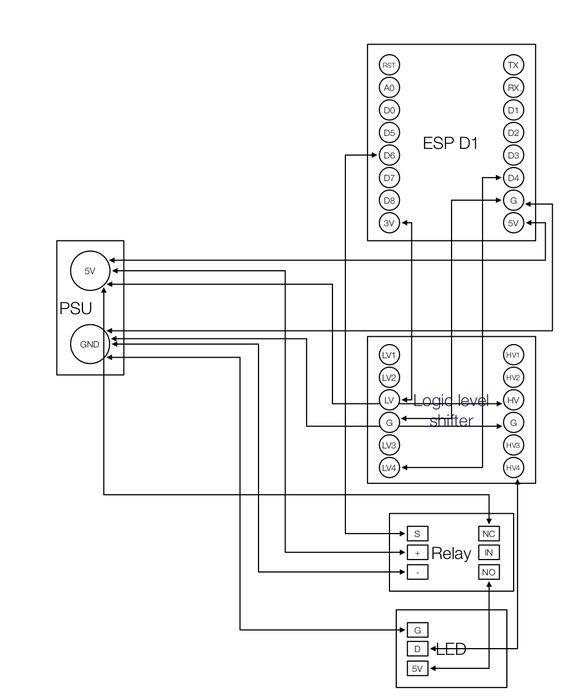
Finally, connect the pins of the components like the diagram shows. PSU means the red and white cable on the side of the PCB as they will be later connected to the barrel jack.
When you have finished this step you should have the following components connected:
- ESP
- Logic level shifter
- Power cables
- Relay
- RGB-connector
Note:
It is possible to leave the level shifter out. But with very few boards (for me 1 out of approx. 20) you can have the problem that the LEDs do not correctly trigger.
Step 2: Wiring the LED-Matrix and Power
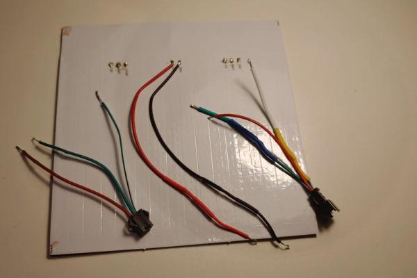
The matrix comes with some connectors already attached. But those do not fit through the holes of the metal case. Therefore unsolder them carefully and solder normal wires on the matrix which fit through the holes.
On the inside of the case there are two larger holes. You can make both of them a little bigger so that on the one side the barrel jack fits in and on the other side the output connector of the LED-matrix.
Before putting the barrel jack in place solder two wires to it like picture 3 shows.
Step 3: Putting It Together
Finally the time to 3D print something has come.
You need a case for the esp/relay and also a spacer for the matrix to be level. On my Thingiverse is a version of a case for the esp and the relay together. And also one with separate cases.
- matrix spacer
- separate cases: “case esp” and “case relay”
- single case
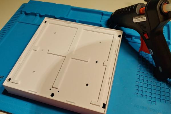
Now print your choice. After the print has finished carefully glue the spacer on the case. The solder points of the matrix need to be isolated too. Therefore drop some hot glue on them. Afterwards glue the matrix on the spacer while routing the wires through the holes of the case.
Now connect all cables and put the extra power input of the matrix in the NO port of the relay.
When everything is finished lookout for shorts in your assembly and put some hot glue on potential ones.
Alternative:
Use glue for everything. Here you have to be very careful that the matrix is level and no conductive material touches the case.
Step 4: Installing the Firmware and Software
Because there is already an awesome open-source software for controlling LEDs with an esp we will be using it. It is called “WLED”
Download the firmware from here. You have to choose the board you have used. If you have followed this guide choose the “WLED_0.x.x_ESP8266.bin” (read more about the differences here).
To flash the software to an esp I will be using the “ESPtool” software. It is free and open software written in python. You can download it here or install it with pip.
$ pip install esptool
Now connect your esp to your computer. You need to figure out the port of your esp. On windows open the “Device manager” and under “Ports (COM & LPT)” you should see the COM-port of your esp.
Back in the terminal, you can now flash the firmware to the esp with:
python -m esptool YOUR_COM_PORT write_flash 0x1000 WLED_0.x.x_ESP8266.bin
If you successfully flashed the firmware you should see an open hot spot called “WLED-AP”. Connect to it using the password “wled1234” and follow the instructions shown to you.
You
can go to the App store/play store and download the WLED app to control your device. It is also possible to integrate it into your home automation system if you have one (take a look here).
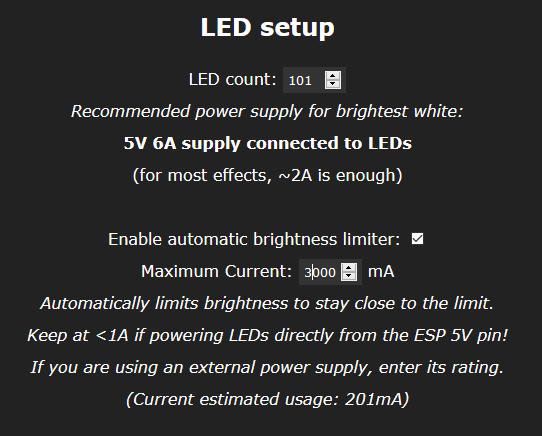
After the download, you have to go in the WLED-app to “Config” → “LED Preferences” and there set the “LED count” to 256 and set the “Maximum Current” to the rated maximum of your power supply. However, if you drive the matrix with too much current it can get damaged. Therefore I recommend 3A.
Now everything is set up and you can enjoy your matrix.
Step 5: (Optional) Using Multiple Matrices
You can use the output of the matrix you have just build to provide an input signal to another matrix. This matrix will not need a second esp either. Just use the holes (which were detailed in Step 3) to connect a second matrix.
If you add more matrices do not forget to adjust the LED count in the WLED-app.
But driving two matrices does require more current and therefore if you add to many lamps you need to add a beefier PSU or even a second, third, etc.
Source: WiFi Enabled Matrix Lamp