Introduction
Our project can be described as a simplified implementation of Wii-Music, utilizing a Nintendo Wii Remote (Wiimote) to play a gesture-based music game with the player as a virtual music conductor.
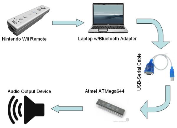
We decided to do this project since it exploited two of the Wiimotes more peculiar features: its wand-like shape and the embedded 3-D accelerometers. Interfacing the Wiimote with a microcontroller (MCU), we wirelessly transmit motion gestures and button pushes to the MCU. The MCU uses these inputs to create sound by means of Direct Digital Synthesis (DDS). Sound is generated whenever the user moves the controller in an up-and-down motion, in true conductor fashion. The sound can be then listened through the connected audio playback device. All of this is done in real time, with all components operating in parallel. Also, since there is little documentation on interfacing the two devices, our project doubles as a guide for future students wishing to do a Wiimote project.

Inspiration
Our original idea was to create a wireless glove interface for cellular phones that operated over Bluetooth. Unfortunately we couldnt find a Bluetooth module that met the specifications we needed (supported the HSP profile, could transmit data serially, AND fit within our $75 budget). Still wanting to do a Bluetooth-related project, we decided on the Wiimote since groups from previous years proved its possible. The idea for a gesture-based music game came after we witnessed another group’s attempt to simulate the movements of a conductors stick (whose permission we made sure to obtain before implementing our idea).
High Level Design
Background Math – DDS Sound Production
The output sound is produced by a method called direct digital synthesis (DDS). Timer0 is set up to create a pulse width modulated (PWM) signal, through the timer0 overflow ISR. The duty cycle, which is determined by the OCR0A register, is cyclical, following a sine wave. The frequency of the output sound is determined by the frequency of the sine wave. For a 32-bit DDS accumulator, running at 16 MHz, the frequency of the sine wave, called the increment in our program, can be calculated by the following formula:
Increment = 2^32*Fout/(16*10^6/2^8) = 68719 * Fout (1),
where Fout is the desired frequency of the output signal. In order to make the output sound better, it is put through a low-pass filter, which converts the output square wave into a sine wave (or sum of sine waves if the output is composed of two or more frequencies). We use a simple first order low pass filter, with R and C values producing a cutoff frequency of roughly 1600 Hz, which is about the same as our highest frequency.
Additionally, the signal is ramped up at the beginning and ramped down at the end in order to remove a glitch (slight click noise) that would otherwise occur. This is achieved by creating a ramp table, and then multiplying this and the sine value together to create a revised OCR0A value.
Prior to data transfer, the Wiimote is linked wirelessly to the laptop via a Bluetooth adapter. The adapter needs to support the Human Interface Device (HID) profile to establish a proper connection. The second figure depicts what happens to the wireless data when it reaches the Laptop stage. After being received by the adapter, the data is captured by GlovePIE and sent to a Visual Basic program via the Open Sound Control protocol. This program is necessary since GlovePIE cant directly transfer data over RS232. Once inside the Visual Basic script, the data is parsed into a usable format for the MCU. Next the data is transferred from Visual Basic to the USB-Serial cable. From there, the parsed data is received by the MCU through a serial connection. The MCU uses the inputted data to create sound based on internal algorithms and state machines. Finally the created sound is played through the connected audio device.
Patents, Copyrights, Trademarks, and Intellectual Properties
Our project incorporates several patents, intellectual properties, and trademarks. Nintendo Company Ltd. owns the rights to the Wii Remote controller, Visual Basic 6.0 is an intellectual property of The Microsoft Corporation. BlueSoleil and GlovePIE are both freeware and intellectual properties of the IVT Corporation and Carl Kenner, respectively. Lastly, our Bluetooth dongle is patented by Iomega, a subsidiary of the EMC Corporation. Since we never modify any of these components there arent any real considerations to be made.
The prototype board that we used for the ATmega644 was designed and laid out by ECE 476 Professor Bruce Land. The initial test code for the prototype board and the UART code used for initializing serial communications were provided as part of earlier labs in ECE 476.
Standards incorporated in our design
Our project references numerous standards, most of which are communication protocols. Some of these communication protocols include Bluetooth, OSC, UDP, and RS-232. Most of these were handled automatically by the various programs we wrote, so long as we followed the appropriate initialization procedures. One additional standard that we used was for outputting sounds is known as dual tone multi-frequency (DTMF). This is the protocol used for outputting sounds that would mimic those produced by a phone.
Software design
Wiimote <-> Laptop Connection
The bulk of our final project, as well as the part that took the most work to design, is our software section. The high level path that data follows begins with accelerometer and button push data being transmitted via Bluetooth from the Wiimote to a program called GlovePie, which runs on a laptop. We use a USB Bluetooth dongle and BlueSoleil drivers. Unfortunately, the Wiimote is incompatible with the inherent Microsoft Bluetooth stack, so the BlueSoleil drivers were required. Luckily, BlueSoleil has a free trial version of their drivers, so this was not a large issue. Once the Wiimote is connected to the laptop, GlovePie is started.
GlovePie
GlovePie was developed by Carl Kenner, in order to facilitate data acquisition of wireless controllers, for example the Wiimote. Programs (with extensions .PIE) are written in a very simple language, similar to C. Following examples that were downloaded along with GlovePie, we easily created a program that acquired the data that we wanted to send to the microcontroller. The first issue we ran into while creating the script was how to do anything with the data. Once the data was obtained by GlovePie, it should then be sent to the microcontroller via a serial connection. We soon discovered that the only way to export data was through a function called sendOSC(), which could send data to a specific IP address/network port number in the Open Sound Control (OSC) format. After researching the differences between network ports and serial ports, we determined that there was no way to send this OSC data directly to the microcontroller.
GlovePie <-> Microcontroller
We then researched different methods of transferring this data from network input to serial output and came up with Visual Basic (VB). VB can listen on a specific network port for incoming data, as well as send data to a specific serial port, which is exactly what we needed. Implementing this crucial step was actually much more difficult than it sounded. Even with numerous guides found online, setting up the input and output sections were difficult to create and debug. When we first began, we looked up every facet of the OSC network protocol, along with serial RS-232 protocol. Unfortunately, this was in vain due to the fact that VB automatically converts the data to and from these protocols without even being told to. Our final GlovePie script obtains six values from the Wiimote, and sends them to the VB program, which then obtains these values, parses them, and sends them on to the microcontroller.
Microcontroller design
At this point, we were back in familiar territory with respect to the programming language. We wanted to design a direct-digital synthesis (DDS) system that would be triggered by the user controlled Wiimote. Thus, we set up pulse width modulation (PWM) to produce the sound, using the timer0 overflow ISR, as well as the receive ISR to read the data from VB. In addition to these two interrupts, we added a state machine that would compare how the up and down acceleration of the Wiimote changes, in order to determine when a sound should be played. To reiterate this part of the design, a sound will be played whenever the user moves the Wiimote down and then up (at the bottom of the movement), similar to how a conductor moves his baton. Our program evolved to include button push inputs, which would do a variety of things. In our final design, we have five buttons: A, B, minus, home, and plus. The minus, home, and plus buttons change what mode the program runs in. Each mode will produce different types of sound.
Default mode, mode 2, or home mode:
In an effort to produce a sound similar to a guitar strumming, we made each output pitch include both its first and third harmonics (with appropriately scaled amplitudes). In this mode, the A and B buttons increase and decrease, respectively, the pitch of the fundamental frequency in half steps. The range is limited to the 13 notes between middle-C and an octave above middle-C, inclusive.
Phone mode, mode 3, or plus mode:
This mode produces the dual-tone multi-frequency (DTMF) sounds that we first experimented with in lab2. In this mode, the A and B buttons cycle through the 12 different possibilities of sounds (1-9, *, 0, #).
Song mode, mode 1, or minus mode:
This mode allows the user to conduct a simple song (Row, Row, Row Your Boat). In this mode, the B button is disabled. The A button must be pushed before any sound can occur: it is the signal that the user is ready to begin the song. The idea of this mode is that every time the user moves the Wiimote down and then up, the output will move to the next note in the song. Once completed with the song, the program will automatically move back to the default mode.
In addition to this, we also included the uart.c/uart.h files in the project, in order to utilize the serial connection between the microcontroller and Visual Basic.
DDS sound production
Timer0 is set to fast PWM mode, which creates an output of a square wave on pin B.3, with a pulse width proportional to OCR0A. Thus, in order to create a wave with a given frequency, we change OCR0A once every timer0 overflow ISR, based upon a sine table. As well, this output is put through a low pass filter (detailed above). In order to increase the quality of the sound, the signal is ramped up at the beginning, and ramped down at the end. This ramping is achieved by multiplying the OCR0A value by a value from a ramp table, which is initialized in initialize(). However, if a user decides to play another note before the previous has finished, no ramping will occur between the two notes. Instead, all sound is cut off for 5 ms, after which, it returns to regular output. This creates a slight pulse of no sound, which is desirable in order to signal to the user when they begin a new note, even if it is the same pitch as the previous.
Wiimote
The hardware side of our project is much less extensive than the software. The first hardware component in the project is the Wiimote. It is a standard wireless joystick device from Nintendo, built to go along with the Wii gaming console. It has a built-in Bluetooth transceiver, which includes the Human Interface Device (HID) profile. We use this profile in order to communicate with it via Bluetooth.
Laptop
The next piece of hardware is the laptop we use. In order to transfer data from GlovePie to the microcontroller, the data must be sent to an internal network port, and then outputted to an external serial port (in this case, we used a USB to serial connector). VB has add-ons to handle both of these protocols, so we didnt have to do anything regarding the actual hardware inside the laptop, luckily.
Microcontroller
Finally, the data arrives at the microcontroller. We decided to create a custom PC board, since it could handle all of the hardware/software issues we needed it to. Using the custom PC board from the previous year, we soldered on all of the usual things according to the how-to on the ECE 476 website, including the mounts for the chip, the power supply, resistors, capacitors, 16 MHz clock, etc. In addition, we needed to be able to communicate with a serial cable, so we added the serial connection and Max233 chip mounts as well.
Debugging
However, when actually testing the program, we used the STK board instead. This was due to our limited debugging ability. Since we were using the serial cable to receive data from the Wiimote, we couldnt utilize the uart output to hyperterm. Thus, all we had was the sound output (if it was working during the current version) and the 8 LEDs on the board. This was one of the most frustrating aspects of the entire project because it cut down our ability to debug so much. When possible, we hardcoded test data into the code, and used the serial cable instead to connect to hyperterm, but in the later testing runs, this proved completely ineffective, as most hard-coded data had to include delays, which blocked the dds-producing ISR.
Sound Output
The dds output data can be played on an array of sound producing devices, from headphones to speakers to TVs. For testing, we used a black and white TV provided in lab.
parts List:
Budget:
Item Vendor Cost Notes
Wiimote Nintendo $0.00 pre-owned
Custom PC Board Bruce Land $2.00 last year�s model
Power Supply Lab $5.00
Max233CPP Maxim $7.00
RS232 connector Lab $1.00 for custom board
AVR ATmega644 Atmel $8.00
DIP socket Lab $1.00 $.50 each
Header socket Lab $0.60 $.05 each
Banana clips Lab $0.00
Circuit board Lab $1.00 2 inch solder board
Circuit board extra parts Lab $0.00 resistors, capacitors, wires
Bluetooth dongle Iomega $0.00 previously owned
USB-Serial connector Lab $0.00
Audio output device Lab $5.00 B/W TV
Inspiron 1300 Dell $0.00 previously owned
Total $30.60
For more detail: Wii Conductor Using Atmega32