Summary of Wireless Connectivity: UNO R3 + WiFi ESP8266 with CH340G Arduino Integration
This project documents an UNO R3 style development board combining an ATmega328 and ESP8266 (with CH340G) to provide easy onboard WiFi for Arduino projects, explains its features, DIP mode switch settings, and step‑by‑step procedures to program the ATmega328 and ESP8266, plus examples showing serial communication between the two MCUs and using an external LED on GPIO12.
Parts used in the UNO R3 WIFI ESP8266 ATMEGA328 CH340G:
- UNO+WiFi-R3-AT328-ESP8266-32MB-CH340G development board
- ATmega328 microcontroller (onboard)
- ESP8266 WiFi module (onboard)
- CH340G USB-to-serial converter (onboard)
- 5V voltage regulator (onboard)
- 3.3V voltage regulator (onboard)
- Micro USB connector (onboard)
- 8-switch DIP mode selection switch (onboard)
- Onboard reset button
- Onboard compact WiFi antenna (with external antenna provision)
- Headers compatible with Arduino Uno R3 shields
- External LED and 330 Ohm resistor (for ESP8266 GPIO12 blink demo)
- USB to Micro USB cable
Utilize the ATMega328 and ESP8266 single-board combination for effortless WiFi integration into your Arduino projects, eliminating the need for cumbersome external connections.
While this particular development board holds several advantages (to be discussed later), it surprisingly lacks extensive documentation. Given its potential as an ideal platform for WiFi-enabled Arduino projects, this project aims to contribute by offering more detailed information.
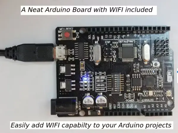
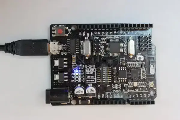
The Arduino ESP8266 WIFI development board
Numerous online platforms such as eBay, AliExpress, and Banggood offer the “UNO R3 WIFI ESP8266 ATMEGA328 CH340G” development board, which can be easily found through a search. This particular board typically costs between 10 to 14 USD before shipping fees. To ensure you’re purchasing the correct product, it’s advisable to compare the image provided in this article with the picture displayed on the selling site.
Here are the high-level specifications of the board:
– Board Model: UNO+WiFi-R3-AT328-ESP8266-32MB-CH340G
– Operating Voltage Range: 6 to 9V
– Microcontroller: ATmega328
– Wireless Connectivity: ESP8266
– USB to Serial Converter: CH340G
– PinOut Compatibility: Uno R3
The image below showcases a detailed description of the components present on the board.
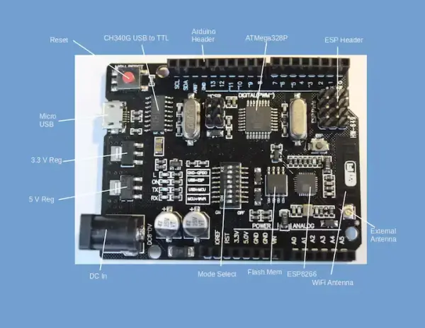
Here are the rephrased notes on the components:
1. The board is equipped with 5V and 3.3V voltage regulators to cater to varying voltage needs for the ESP8266 and ATMega328.
2. Instead of employing the conventional Arduino’s large USB connector, this board utilizes a micro USB connector for serial communication and programming.
3. The Reset button serves to reset both the ESP8266 and ATMega328.
4. The header pin out follows the standard Arduino configuration, enabling the connection of any Arduino-compatible shield to this development board.
5. The board is furnished with a compact WiFi antenna. If extended range is desired, provisions exist for attaching an external antenna.
Advantages of The Arduino ESP8266 WIFI development board
This particular board offers numerous advantages compared to similar solutions, particularly the WeMos D1 board.
The Arduino pin configuration enables seamless connections with a wide array of available Arduino shields.
Built-in board features handle various voltage levels effortlessly, providing a user-friendly experience.
It simplifies the integration of WiFi communication within Arduino projects.
With two processors integrated into the board, users have access to a broader spectrum of processing capabilities.
Communication between the ATMega328 and ESP8266 occurs through serial lines, utilizing the widely recognized Serial library.
Mode Selection
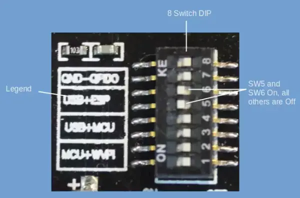
The Mode Selection switch, comprising an 8-switch DIP positioned at the board’s center, is fundamental for the board’s functionality.
The mode switch provides four potential configurations:
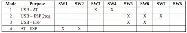
1. Mode 1 – Utilizes USB Serial linked to ATMega328 for programming and serial communication.
2. Mode 2 – Employs USB Serial connected to ESP8266 solely for programming.
3. Mode 3 – Uses USB Serial connected to ESP8266 solely for serial communication.
4. Mode 4 – Establishes serial connection between ATMega328 and ESP8266, facilitating communication between both devices. Voltage disparities between the Arduino and ESP8266 are managed within the board.
The ESP8266 necessitates grounding GPIO0 during programming, a requirement not applicable to the ATMega328. Consequently, two distinct modes are designated for the ESP8266, activated by switching SW7 to ground GPIO0.
The DIP switch configurations for these modes are outlined in the table below:
DIP Switch Settings for Different Modes.
X = Switch On
Blank = Switch Off
The board has a legend showing the switch settings.
Programming the ATMega328
As an initial demonstration, we’ll initiate programming for the ATMega328 using the Blink Sketch. Follow these steps:
1. Power down the board by disconnecting it from the power source.
2. Utilize a paper clip, pencil point, or any other pointed device to adjust the switches to Mode 1. This configuration entails turning on SW3 and SW4 while keeping all other switches off.
3. Access the Blink Sketch within the Arduino IDE by navigating to Examples → Basic.
4. Establish a connection between your computer and the board by plugging in the Micro USB port using a USB to Micro USB cable.
5. Upload the Sketch to the board.
6. The ATMega328 will undergo an automatic reset, prompting the LED labeled “L” to commence blinking.
This sequence confirms the functionality of the ATMega328, indicating successful programming. Simple and effective.
Programming the ESP8266
Preparing the ESP8266 for programming via the Arduino IDE requires specific configuration steps. To ensure a smooth process, it’s essential to set up the Arduino IDE appropriately. Multiple online resources detail these steps, and a simple search using keywords like “programming ESP8266 from Arduino IDE” will yield numerous helpful articles.
Refer to the following links for detailed guidance:
1. https://www.instructables.com/Setting-Up-the-Arduino-IDE-to-Program-ESP8266/
2. https://randomnerdtutorials.com/how-to-install-esp8266-board-arduino-ide/
The fundamental procedure involves:
1. Access File → Preferences in the Arduino IDE and include the following URL in the Additional Boards Manager: http://arduino.esp8266.com/stable/package_esp8266com_index.json
2. Navigate to Tools → Boards → Boards Manager, search for ESP8266, and install the most recent version of “ESP8266 by ESP8266 Community.”
3. Once completed, under Tools → Board, an option for ESP8266 Boards will be available. Select “Generic ESP8266 Module.”
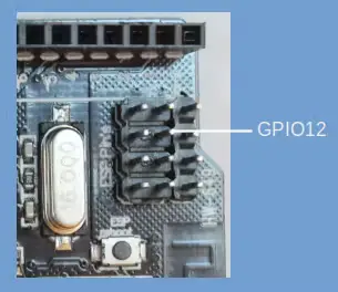
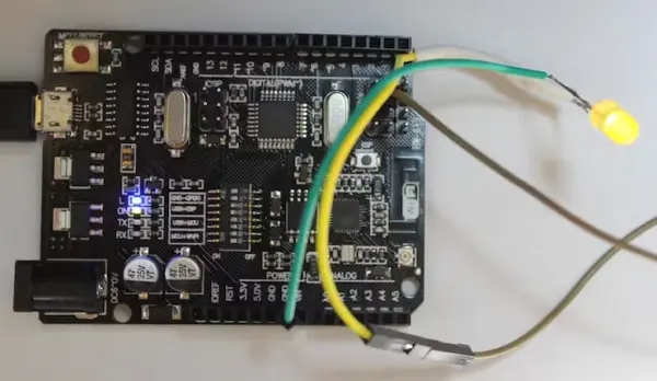
With these configurations in place, you’ll be set to execute a Blink program on the board. Notably, the ESP8266 on this particular board lacks a built-in LED, necessitating the connection of an external LED to demonstrate the Blink program’s functionality.
The board’s ESP header provides access to GPIO12 from the ESP8266, designated for LED connection. Detailed pin functions are specified on the board’s rear. Connect a 330 Ohm (or similar) resistor and an LED in series between GPIO12 and the GND pin on the Arduino header to showcase the Blink program’s operation.
Proceed with the outlined instructions:
1. Ensure that the Arduino IDE is configured for the Generic ESP8266 Module.
2. Power off the board. Adjust the switches to Mode 2, wherein SW5, SW6, and SW7 are set to On, while all other switches are set to Off.
3. Connect the Micro USB port to your computer using a USB to Micro USB cable.
4. Proceed to upload the Sketch Blink for ESP8266.
/*
  ESP8266 Blink
  Blink the LED on the ESP8266 module
  This example code is in the public domain

  The external LED on the ESP8266 module is connected to GPIO12

*/

void setup() {
  pinMode(12, OUTPUT);     // Initialize pin 12 which is GPIO12 as an output
}

// the loop function runs over and over again forever
void loop() {
  digitalWrite(12, LOW);   // Turn the LED off
  // low is off on the ESP8266-12
  delay(1000);                      // Wait for a second
  digitalWrite(12, HIGH);           // Turn the LED on by making the voltage HIGH
  delay(2000);                      // Wait for two seconds (to distinguish between low and high)
}
Second Sketch
bool toggle;
String incomingString;

void setup() {
  pinMode(12, OUTPUT);     // Initialize pin 12 which is GPIO12 as an output
  toggle = false;

  Serial.begin(115200);   //All serial communication with ESP8266 at 115200 baud
}

void loop() {

  if (Serial.available() > 0){
    // read the incoming string from the Arduino
    incomingString = Serial.readString();

    // If the incoming string from the Arduino equals "change" then we toggle the LED
    if (incomingString.equals("change")){
      digitalWrite(12, toggle);  // Turn the LED off or on
      toggle = !toggle;
    }
  }
  delay(50); // Wait for half second
}
Upon successful completion, the Arduino IDE will display the message: “Hard resetting via the RTS pin.”To exit the programming mode of the ESP8266, disconnect power from the board and switch off SW7 by toggling it to the off position.
Communicating between the ATMega328and ESP8266
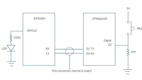
The bidirectional serial bus present in both the ATMega328 and ESP8266 allows them to communicate with each other. This communication enables data exchange in both directions: the ATMega328 can transmit information to the ESP8266, and vice versa.
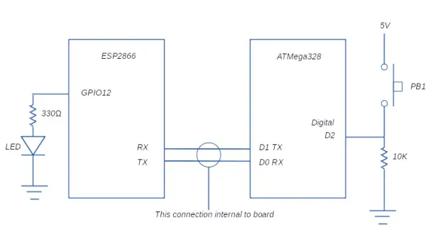
For illustration, a straightforward circuit linked to the ATMega328 has the capability to trigger an LED connected to the ESP8266. Refer to the circuit diagram provided below.
Here are the rephrased programming steps:
1. Ensure the DIP switch is set to Mode 1 (SW3 and SW4 are On) with the power turned off. Apply power and upload the Arduino Sketch named “ArduinoESPCommunication.”
2. Turn off the power and adjust the DIP switch to Mode 2 (SW5, SW6, SW7 are On). Switch the Arduino IDE to ESP8266 programming mode and upload the sketch named “ESPReceiveCommunication.”
3. Turn off the power again and configure the dip switch to Mode 4 (SW1 and SW2 are On). Finally, restore power to the system.
const int buttonPin = 2;     // the number of the pushbutton pin
int buttonState = 0;
void setup() {

// Initialize the pushbutton pin as an input:
  pinMode(buttonPin, INPUT);
  pinMode(LED_BUILTIN, OUTPUT);

  Serial.begin(115200); //All ESP8266 serial communication at 115200 baud
}

void loop() {
  // read the state of the pushbutton value:
  buttonState = digitalRead(buttonPin);

  // check if the pushbutton is pressed. If it is, the buttonState is HIGH:
  if (buttonState == HIGH) {
    // Send a message to the ESP8266
    Serial.write("change");
    // Flash the built in LED to confirm that button push was registered
    digitalWrite(LED_BUILTIN, HIGH);   // turn the LED on (HIGH is the voltage level)
    delay(500);
    digitalWrite(LED_BUILTIN, LOW);    // turn the LED off by making the voltage LOW
    delay(250);

  }
  else {
    delay(25);
  }
}
Depressing the push button triggers the flashing of the ATMega328’s built-in LED while activating the LED linked to the ESP8266.
Subsequent button presses initiate another cycle: the built-in LED flashes, and the LED associated with the ESP8266 turns off.
To enable communication between the ATMega328 and the ESP8266, utilize the Serial.write(“change”) and Serial.readString() commands. For a comprehensive understanding, refer to the provided sketches for detailed information.
Schematics
- How do I program the ATMega328 on this board?
Set DIP switch to Mode 1 (SW3 and SW4 On), connect via Micro USB, select the ATmega328/Arduino settings in the Arduino IDE, and upload the sketch; the L LED will blink after automatic reset. - How do I program the ESP8266 on this board?
Install ESP8266 boards in the Arduino IDE, select Generic ESP8266 Module, set DIP switch to Mode 2 (SW5, SW6, SW7 On), connect via Micro USB, and upload the ESP sketch. - How do I run a Blink sketch on the ESP8266 since it has no built-in LED?
Connect an external LED with a ~330 Ohm resistor between GPIO12 and GND (GPIO12 exposed on the ESP header) and run the Blink sketch targeting pin 12. - What do the DIP switch modes do?
The DIP switch selects USB serial routing and MCU interactions: Mode 1 programs ATMega328 via USB, Mode 2 programs ESP8266, Mode 3 uses USB for ESP8266 serial, and Mode 4 links ATMega328 and ESP8266 serially for intercommunication. - How is GPIO0 handled for ESP8266 programming?
The board grounds GPIO0 when required by setting SW7 On, enabling the ESP8266 programming mode distinct from ATMega328 programming. - Can the ATMega328 and ESP8266 communicate with each other?
Yes; they communicate over a bidirectional serial bus. Use Serial.write on one side and Serial.readString on the other to exchange commands like change to toggle an LED. - What voltage support does the board provide?
The board includes both 5V and 3.3V regulators to support ATmega328 and ESP8266 voltage needs and manage level differences between them. - How do I switch between programming modes and run inter-MCU communication?
Program ATMega328 in Mode 1, program ESP8266 in Mode 2, then set DIP to Mode 4 to enable serial communication between the two and power the board.