Related projects
At least two other approaches exist to accomplish this. Both of them are using the similar Prism chip based WLAN cards. But none of these projects is fully documented nor fully working.
The approach being part of the Procyon AVRlib is a pure software solution. This means that the AVR does the entire compact flash communication timing in software. This is unfortunately slow, unreliable (due to an inexact timing) and consumes plenty of those precious IO ports on the AVR. Furthermore it lacks a description of the hardware needed.
The second approach is a WLAN hardware add-on to the ethernut board. It uses PCMCIA WLAN card and an FPGA to achieve hardware supported reliable transfers, but the hardware is only partially documented and the entire project has been discontinued due to unsatisfying performance.
Thus i decided to build my own system. I wanted it to be as small, simple and cheap as possible while leaving much of the AVR functionality for other use and allowing fast and reliable WLAN data transfers. The final design was based on a prism chipset based compact flash WLAN card which is connected to the AVR CPU using a programmable logic chip (CPLD) made by Xilinx. Since the CF card is attached to the AVR using the SPI interface the entire system is named the SPI2CF project. You can get the complete compact flash specification from the Compact Flash Association.
The pros and cons of this solution presented here are:
Pros:
- Reliable CF data transfers
- Simple and easy SPI AVR interfacing
- Fast transfers with low cpu impact
- Homebrew friendly hard and software (all required tools are free of charge)
- Can be used for other compact flash cards as well
- Support for uip TCP/IP stack
Cons:
- Requires the ability to flash a CPLD
- Uses outdated WLAN hardware
Why not use an SD, USB or PCI card?
There’s a huge problem with WLAN: A lack of hardware documentation. A WLAN SDIO card would be great inconjunction with the AVR CPU. Although the SDIO standard comes under NDA and requires expensive licensing, the SPI related subset of SDIO is freely available. While this isn’t the fastest way to access an SDIO card it’s still fast enough for a simple AVR based system. Such a solution would only consume a few pins on the AVR and would allow for quite a nice hardware design making use of the AVRs built-in SPI capabilities. Unfortunately none of the WLAN SD card manufacturers i contacted were willing to privide the necessary information to do this. And without such a documentation the only way to do this would be massive reverse engineering which i wasn’t willing to do.
I am still interested in this. So if you can get detailed information on an SDIO WLAN card i am willing to try this. The documentation required is a detailed command description incl. the entire command set supported by such a card with a detailed description on how to use these commands to initialize the card and to send and receive data packets is required. Please don’t ask me if i have gotten this information already. As soon as i get it i will state so here.
Other interfaces like USB and PCI need very fast and complex interfacing and can’t easily be attached to a small 8 bit AVR microcontroller.
What CF WLAN card to use?
Thus the most useful remaining option was to use prism chipset based CF cards since all the documentation to use them has been available to open source programmers and e.g. the authors of the linux kernel and the Procyon AVRlib have had access to these. Unfortunately these cards are rarely produced today. Cards known to fall into this cathegory are the Pretec WL-201 and the Netgear MA701. Other cards may exist but haven’t been tested. The interface specification for the compact flash slot can be downloaded (after registration) from the web site of the compact flash association, prism chipset information can easily be found on the internet using your favorite search engine (e.g. here).
System overview
The entire system consists of three main function blocks: The AVR as the central CPU running the high level network routines including the TCP/IP stack. The second main block is the compact flash WLAN card running all the low level network functions including encryption. The third block is a XC9572XL CPLD, a programmable logic device that forms the spi2cf interface between the AVRs SPI and the CF card. It is mainly doing the translation between the SPI interface used to connect to the AVR and the parallel interface used on the compact flash slot.
SPI2CF concept
The CPLD based spi2cf chip makes sure that the SPI accesses cycles of the AVR are being translated into the correct CF timing. This is the main reason why CF cards driven by a pure software solution are often somewhat unreliable. These solutions cannot exactly meet the CF timing constraints when doing the necessary IO timing “manually” in software. The spi2cf CPLD circumvents such problems.
The remaining parts are simple helper parts like the MAX232 level shifter required for a RS232 compliant serial interface and the 4053 multiplexor used to share some of the AVRs IO lines between the CPLD and the AVRs own programming interfaces.
Power supply
Prism WLAN cards usually require 3.3V for power supply. The XC9572 CPLD is available in two versions, the XC9572 runs at 5V, the XC9572XL at 3.3V. Finally the AVR ATmega32 is available in both, a 5V and a 3.3V version as well. It’s therefore possible to build the entire system from 3.3V devices only. This has the small disadvantage that the 3.3V AVR CPUs cannot be clocked as high as their 5V counterparts. In order to run the AVR at e.g. 16MHz it must be powered at 5V. But the inputs of the 3.3V XC9572XL are 5V tolerant and the 5V AVR will accept 3.3V on its inputs. It’s therefore possible to directly connect a AVR running 5V to a XC9572XL CPLD running at 3.3V. The CPLD thus works as a simple level shifter. The demo system uses this possibility and operated the CPU at 5V.
Power consumption
The prototypes draws about 250mA at 5V with the Pretec card installed and initialized but not sending. When doing full speed bidirectional communication the power consumption increases to 400mA.
External interfaces
The development board features a whole set of physical connections despite the fact that it’s meant to be wireless. Fortunately these cables are only required during development. The RS232 interface is used to output debug information from the AVR to the PC. The AVRs programming interface is being used to upload program code to the AVRs internal persistent flash memory. The CPLD features a similar programming interface which is being used to upload functional configurations to the CPLDs internal flash cells. The AVRs as well as the CPLDs flash memory keep their information permanently. Thus any programming needs only to be done once. Once the development is finished the device becomes truly wireless.
For further information about the homebrew use of the Xilinx XC9572XL CPLD see e.g. Thomas Fischls pages (german).
Internal interfaces
The three main devices are coupled via two interfaces: The serial peripherial interface (SPI) is used to connect the CPLD to the CPU and a compact flash (CF) interface is used to interface the CPLD to the compact flash card. The CPLD thus basically translates between SPI and CF and is therefore named SPI2CF. Read more details here.
The prototype hardware
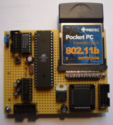
The parts for the demo hardware can easily be obtained from companies like e.g. Reichelt and everything can be installed on a breadboard. The only problem may be the compact flash slot. I bought two cheap PCMCIA to CF interface cards, carfully opened them, removed the CF slot and placed it on the breadboard. See below for the complete schematics and some snapshots of my prototype.
The schematic of the final PCB (click to enlarge)
The prototype shows nicely that only a few connections are required between the AVR and the CPLD. The entire hardware fits onto a 10cm * 8cm breadboard. The schematic above is the one for the final PCB. The difference to the prototype is just a different pinout of the chips due to the different chip packages used in the prototype and the final hardware.
The final hardware
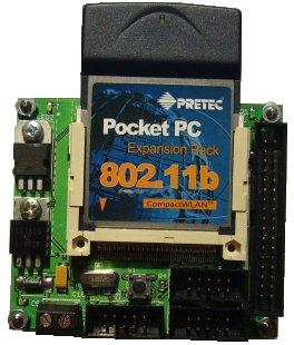
The final hardware is based on SMD components only. Thus the entire PCB isn’t significantly bigger than the CF card itself.
For more detail: Wireless Lan for AVR microcontrollers

