Our wireless music player allows the user to listen to uncompressed digital audio streamed over a wireless link.
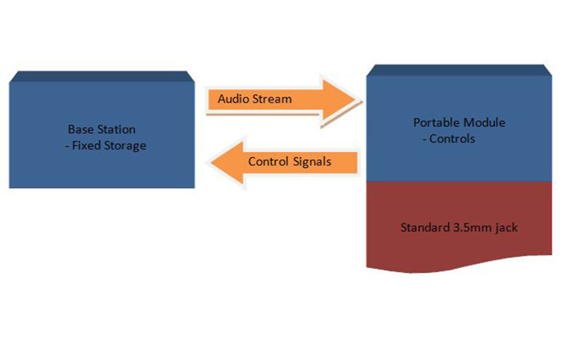
The music player reads uncompressed audio data from an SD card in an immobile “base station.” A pair of Xbee transceiver modules are used to stream data and control signals between the base station and a portable module. The battery powered portable module can be connected to speakers at any location within 30 feet of the base station.
Overview
Rationale:
In recent years, advances in solid state storage and the steady increase in the density of magnetic storage devices have made large data capacities readily accessible. In spite of these advances, the data storage circuitry in a portable music player occupies a considerable amount of circuit board space. This tends to make music players bulky. In addition, the means of storage consume a signficant amount of power, limiting battery life. Both of these factors reduce the portability of music players.
By moving music storage to a fixed module, we can remove these drawbacks. The storage module can draw its power directly from the residential mains supply, thus extending the battery life of the portable module. Inspired by networked media center products, we decided to implement a wireless link between this storage module and a portable module for maximum usability. Many wireless headphones already provide audio streaming functionality by utilizing bluetooth. However, these headphones typically have limited range. In addition, the music player itself needs to be kept close at hand for controlling playback. By implementing a bidirectional wireless link (see Figure 1 below), our portable module allows the user to remotely control playback.
High-level Design:
This project used an Atmega644 microcontroller clocked at 20MHz in each of the two functional modules for processing. Memory storage is provided by a standard Secure Digital (SD) card. Xbee modules provide bidirectional wireless communication and we use the TLV5616 DAC chip for generating analog audio. The LM358 dual op amp provides active filtering to the output of the DAC. Music files can be added to the SD card using any computer with a multimedia card reader. Once the base station detects an SD card inserted into the holder, it awaits data requests from the portable module. The portable module requests data when required and feeds these values into the DAC. The DAC output is low-pass filtered by the op amp, which also buffers the DAC output before it reaches the audio output jack.
The portable module can send navigation commands (play, stop, next track or previous track) to the base station, where they are implemented. These control signals are transmitted over the Xbee as well. The SD card and Xbee modules operate at 3.3V, while all our other hardware required a 5V power supply. Extra power regulation was required to enable the use of these devices. In addition, we needed circuitry to allow 3.3V devices to interface safely with 5V microcontrollers while allowing a throughput on the order of several hundred kilobits per second.
Trade-offs:
Initially, we had planned to use an mp3 decoder IC in our project. However, the chip we obtained did not work and debugging it took up a lot of our design time. We then decided to stream in the uncompressed .wav data format instead.
Since streaming audio is a very bandwidth intensive task, it is hard to accomplish with cheap RF hardware. We had thought about transmitting the audio as an amplitude-modulated analog wave. However, this mode of transmission would be very sensitive to environmental noise. Since the Xbee modules offered enough bandwidth to get passable audio quality with a digital transmission method, we decided to use them instead.
The RF baud rate of the Xbee modules we used was 250 Kbps. However, the overhead of the 802.15.4 protocol meant that the actual maximum transfer rate attainable was much lower. Due to this limitation, we had to limit our music data to a resolution of 8 bits at a sampling rate of 8 KHz. This resulted in a net required bandwidth of 64 Kbps for consistent audio playback. The 8 bit resolution of the music data reduced the quality of the sound, but the limitation was a necessary consequence of our wireless hardware and the lack of any usable audio compression schemes.
Standards and Copyrights:
This project used the IEEE 802.15.4 standard for the wireless link. We used a pair of Xbee devices that implement this protocol. SD card technology is patented and use of the SD mode interface requires an expensive license. We used the SPI interface instead, which lacks access to encryption and speed features available in the SD interface, but is free to use. The SD cards used were formatted in the FAT file system. Part of the FAT standard is patented by Microsoft, but it pertains to implementing long file name extensions in devices made for sale. We did use the file name extension feature of FAT in our software. However, we are not planning on commercializing our music player, so the patent does not apply in our case.
Hardware
Base Station:
- Xbee Transceiver Module
– This module provides wireless communication to/from the base station and the portable module at the ISM band of 2.4 GHz. The four pins connected are 3.3V, ground and the serial communication lines. - Microcontroller Board
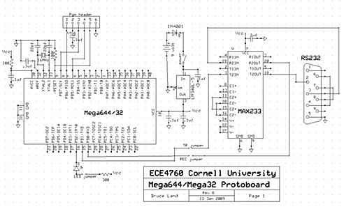
– The standard 4760 prototyping board pictured above is populated with an Atmega644 microcontroller clocked at 20 MHz. The serial transceiver and DB-9 connector have been soldered on for debugging purposes. They remain unused in the final implementation. The board accepts a 9-12 V input and regulates it down to 5 V for the on board microcontroller. A 0.1 inch header has been soldered into the row of breakout vias along one edge to allow it to plug directly into a breadboard. The onboard programming header allows in-situ reprogramming of the microcontroller’s flash. - Level Transceiver
– This circuit allows the 3.3 V SD card to interface with a 5 V microcontroller even at high bus speeds. The circuit is illustrated in the schematic below.
- The 5 V output signals from the microcontroller are reduced in voltage by means of a simple voltage divider with appropriate resistor values. The 3.3 V output signals from the SD card are shifted up to 5 V by means of a transistor-based level shifter to keep rise times within the SPI spec.
- SD Card
– SD cards with music files can be plugged into this Molex SD card holder. The card holder is soldered to a small piece of perfboard. The perfboard has a 0.1 inch header connected to the pins of the card holder. This header can be used to indirectly plug the surface mount SD card holder into the base station’s breadboard. The holder itself is spring loaded, allowing easy removal and insertion of SD cards. - 3.3 V Regulator
– The LT1587 linear regulator receives a 5 V input from the microcontroller board and regulates it down to 3.3 V for the SD card and the Xbee module.
Portable Module:
- Microcontroller Board
– The standard 4760 prototyping board pictured above is populated with an Atmega644 microcontroller clocked at 20 MHz. The serial transceiver and DB-9 connector have been soldered on for debugging purposes. They remain unused in the final implementation. The board accepts a 9-12 V input and regulates it down to 5 V for the on board microcontroller. A 0.1 inch header has been soldered into the row of breakout vias along one edge to allow it to plug directly into a breadboard. The onboard programming header allows in-situ reprogramming of the microcontroller’s flash. - Xbee Transceiver Module
– This module provides wireless communication to/from the base station and the portable module at the ISM band of 2.4 GHz. The four pins connected are 3.3V, ground and the serial communication lines. - 9 V Alkaline Battery
– The alkaline battery provides enough power to run the portable module for about four and a half hours. - Output Filter
– This circuit uses an LM358 dual op amp to implement two cascaded multiple-feedback (MFB) topology low-pass filters. The cutoff frequency for this filter is 3 KHz, which is a little below the Nyquist frequency of our audio DAC to allow for increased attenuation of out-of-band frequency components. The circuit is implemented as shown in the schematic below:
- We chose this topology from among a number of other candidates for its low passband ripple, which makes it suitable for audio applications. We used a filter design wizard provided by Texas Instruments for calculating the component values required for this filter.
- Digital-to-Analog Converter
– The DAC we used in our application was the TLV5616, which provided a maximum of 12 bits of resolution and a sample rate of up to 100 KHz. While not an audio-oriented DAC, this chip has an easy-to-use SPI interface and provides greater resolution and higher sample rates than we were planning on using in our music player.
For more detail: Wireless Music Player Using Atmega32


