Summary of Wireless Outlet Controller
This project hacks a standard wireless outlet remote to enable voice-controlled automation using a Particle Photon. By soldering wires to the remote's circuit board and connecting them to an 8-channel relay module, the system emulates button presses wirelessly. This setup allows users to control multiple outlets via Alexa and IFTTT without the mess of individual wiring for each device, offering a cost-effective alternative to commercial smart plugs or complex DIY relay banks.
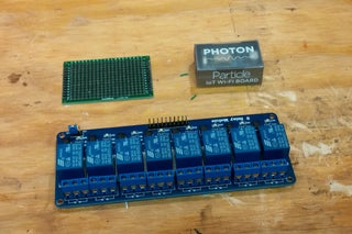
Parts used in Wireless Outlet Controller:
- Particle Photon With Headers
- 8 Channel 5v Relay Module
- ETekcity Wireless remote control outlet set of three
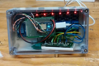
- Clear top waterproof project box
- Small double sided prototype board
- Various wires
- IFTTT Account
- Micro USB Cable
- USB Power Supply
I Like Internet of Things. I like Automation in general. One issue i have with most outlet control systems is that you only have the choice of a per outlet solution like zwave through smart things. Or a DIY Solution using something like a Particle Photon and a Relay bank. The problem with the particle photon and a relay bank is that everything must be within a close proximity to the relay bank as they must be individually wired to the relay bank and a power source. This can make for a mess, to say the least.
So this is my solution. I am making a way to control multiple outlets using wireless. Using a preexisting product that inexpensively makes 3 outlets RF wireless. We will hack the controller and make it controllable using a particle photon with a relay.
Step 1: Gather Your Materials,,, or “what Do I Need to Buy Again?”
Here are the materials i used to make this
- Particle Photon With Headers — Adafuit
- 8 Channel 5v Relay Module — Amazon – $8.98
- ETekcity Wireless remote control outlet set of three — Amazon – $22.98
- Clear top waterproof project box — Amazon – $14.21 (did not need to be this hefty, this is just what i had on hand
- small double sided prototype board
- various wires
- IFTTT Account
- Micro USB Cable
- USB Power Supply
Step 2: Wiring This Thingy Up,, or “Connect the Dots” for Electrical Engineers

The Particle and the Relay
So wiring this up is really easy. The relay has a 5v, pin in 1 through 8 and aground pin. Easy right? Gound and voltage on the relay go to vcc and gnd on the particle photon. The signal pins need to be wired to the digital pins on the photon. It really does not matter which digital pin goes to which signal pin,,but, i would recomend putting 1 to 1 and 2 to 2 and so on and so forth. I did not do this and had to create a “map” of sorts to make sure i would not get any more confused.
The Wireless Outlet Remote
As for the remote control, you need to solder wires to the back of the circuit board for the remote. The easies way to make sure that you are soldering to the correct leads is to short 2 of the pins on the back of each button untill the intended action happens. For example, set it up and then short two of the pins on the “on” button for one of the outlets. When the outlet turns on then those are the two leads that you need to solder to. these leads will go into the Normally Open and Common ports for a relay. Each Switch (1 on, 1 off, 2 on, 2 off, 3 on, 3 off) will need its own relay. If you were able to find a remote with a push once to turn on and push again to turn off type of remote then you would only need a single relay per outlet.
Step 3: Setting Up and Programming the Photon,, or the “boring Part”
Im not going to go through the entire setup of a particle photon as i have gone into detail as to how to set it up and program is in another instructible located here.
Needless to say, after the photon is set up you will have to go to the website build.particle.io to program the photon. I have included the code in a .ino file above. The code is really simple, it uses a “parse” command. meaning that it is waiting for a command. The command specified is “ENABLE” Followed by the digital pin that you want to trigger. The delay in the code makes it so that the relay does not stay on. It emulates a key press, or in this case a remote button press. So for example if relay 1 is hooked to Digital pin 1 on the photon, then the command ENABLE 1 will pull the pin high for 200 milliseconds and then put it back low effectively resetting it.
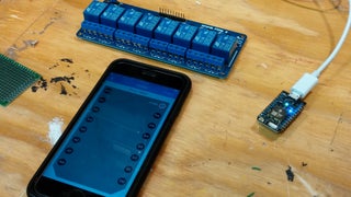
IFTTT is a website that allows you to create “recipes” that automate things. we will make a recipe to make it so when we tell alexa “trigger turn on xxxxx” it will tell particle to trigger the function we created. Sign up / in to www.ifttt.com and create a new applet with alexa as the “if” and particle as the “that”.
Make sure when you are creating the applet and it asks for the function for the particle you type “ENABLE” and then the pin #, so for D7 type “ENABLE7” and for D6 type “ENABLE6” . Remember, you will have to create two separate recipes for each digital pin.
Source: Wireless Outlet Controller
- How do you identify the correct leads to solder on the remote?
Short two pins on the back of each button until the intended action happens. - What command does the Particle Photon code wait for?
The code uses a parse command waiting for ENABLE followed by the digital pin number. - How long does the relay stay active when triggered?
The relay stays high for 200 milliseconds to emulate a key press before resetting. - Can one relay control both on and off functions for a single outlet?
No, each switch requires its own relay unless using a specific push-on-push-off remote. - Which website is used to create automation recipes with Alexa?
IFTTT is used to create applets where Alexa triggers the Particle function. - What format should be typed into the Particle function field for D7?
You must type ENABLE7 to trigger the specific digital pin. - Why might a map be needed if digital pins are not matched sequentially?
A map is needed to track which digital pin corresponds to which signal pin to avoid confusion.