
Summary of Yet Another Semiconductor V/I Curve Tracer – I
This article discusses the design and operation of a semiconductor curve tracer, a tool used to generate V-I characteristics for devices like BJTs. While largely replaced by digital tools, it remains popular in education and among hobbyists. The device uses a staircase waveform for base current and a sweep voltage (often rectified AC) for collector-emitter voltage.
Parts used in Semiconductor Curve Tracer:
- NPN Transistor
- Base Resistor R2
- Staircase Waveform Generator
- Sweep Voltage Source
- Transformer
- Bridge Rectifier
- Current Sensing OpAmp (Optional)
- Variable Current Source (Alternative Option)
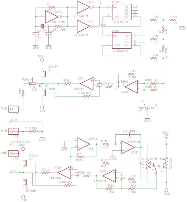
Semiconductor curve tracers were frequently used in analog circuit designs many decades ago, at a time when discrete semiconductor devices were in dominance and ICs were scarce. While curve tracers are no longer widely used nowadays due to the ubiquity of digital circuitry and computer aided designs, they are still quite popular in the educational world and among hobbyists. In this and the next post, I will discuss some of the design considerations of a curve tracer that I built and show some real-world measurement results.
A typical use of a curve tracer is to generate the V-I characteristics of the device under test (DUT). The following diagram illustrate how a typical configuration works when the DUT is a BJT.
In the figure above, a staircase waveform is fed into the base of a NPN transistor via a base resistor R2. For each step in the waveform, a different base current (Ib) is generated. When the input waveform voltage is sufficiently large, the voltage drop between the base and emitter junction (Vbe) can be ignored and thus:
where Vbi is the voltage of the ithstaircase. This arrangement is usually good enough for most cases and this is what I used in my design as well. If we need more accurate characterizations of different Ib’s, we can either use a variable current source (which increases the circuit complexity) in place of the staircase waveform generator or simply use the same design but add a current sensing OpAmp to read back the actual base current.
A sweep voltage is applied between the collector and the emitter. The sweep waveform is usually a symmetrical triangular wave so that characteristic curves for both sweep directions can be captured. When we only care about the characteristics in one direction (say when the voltage is ramping up) we could use a sawtooth waveform instead. The linearly of this swept waveform is not significantly important, and in many curve tracer implementations (like this one) the sweep waveform is simply bridge-rectified from the transformer directly. Since the rectified AC signal is sinusoidal, the end of the curve tends to be brighter than the rest of the curve compared to that using a triangular swept signal.
For more detail: Yet Another Semiconductor V/I Curve Tracer – I
-
What is the primary function of a semiconductor curve tracer?
A typical use is to generate the V-I characteristics of the device under test. -
How is the base current generated in the described BJT configuration?
A staircase waveform is fed into the base via a resistor to create different base currents for each step. -
Can the base voltage drop be ignored during operation?
Yes, when the input waveform voltage is sufficiently large, the voltage drop between the base and emitter junction can be ignored. -
What type of waveform is typically applied as sweep voltage?
The sweep waveform is usually a symmetrical triangular wave to capture characteristic curves for both sweep directions. -
How is the sweep waveform often generated in this specific implementation?
The sweep waveform is simply bridge-rectified from the transformer directly using the rectified AC signal. -
Why might the end of the curve appear brighter in some implementations?
Since the rectified AC signal is sinusoidal, the end of the curve tends to be brighter compared to using a triangular swept signal. -
What alternative method improves accuracy for characterizing different base currents?
You can use a variable current source or add a current sensing OpAmp to read back the actual base current.
