This is the seventh part of an ongoing series about building a low cost, open source streaming internet radio. If you haven’t already, check out the previous parts (see the links at the end of this article) for some background about the project.
In part six, we used OpenWrt’s UNIX-style shell commands to interface with mpd, the music player daemon, and redirect song and stream information to our ASUS WL-520gU wireless router’s serial port. In this part, we’ll use a Sparkfun 16×2 LCD display and a handful of other components to build an LCD status display for the radio.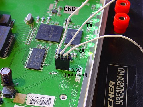
The Atmel AVR Microcontroller:
After much thought, I decided to use an Atmel ATmega168 AVR microcontroller to drive the display. I realize that this raises the technical level of this project significantly, but I have been wanting to feature an AVR project on the site and this is a great opportunity. The truth is that an Arduino would work just as well and it shouldn’t be too difficult to port this program to an Arduino sketch. (The Arduino is built with the same ATmega168 microcontroller, after all.) If anyone does this, let me know and I’ll post a link to your version of the display.
If you’re an AVR veteran, you can skip over this part and straight to the bill of materials below.
If you are new to the AVR, don’t be intimidated. There are a number of tutorials online to help you learn how to use this inexpensive and powerful microcontroller. I recommend starting with this one or maybe this one, but see my note about AVR MacPack below if you’re using a Mac. If you’ve never programmed in C before, you’ll have an additional hurdle to get over, although for this project you won’t need any actual knowledge of programming or C to burn the code to the AVR and get things working.
You will need to install some software to work with the AVR, I recommend:
- AVR MacPack for OS X (the Adafruit tutorial recommends OSX-AVR, use this instead)
- WinAVR for Windows
I recommend following a tutorial or two and getting a simple blinking LED example working on your AVR before building the LCD display. That way you can be sure your programmer, development environment, breadboard, etc are working first.
Building the display:
Bill of Materials:
You will need:
- one A-B USB cable (the kind with one flat and one square end)
- an AVR programmer, such as the Adafruit USBTinyISP
- an Atmel ATmega168 AVR microcontroller
- a working AVR development suite or at least a way to get a .hex file onto an AVR (see above)
- an LCD display like this fancy LED backlit Sparkfun 16×2 Character STN
- a solderless breadboard, like this one (comes with precut wires!) or this one.
- a 4-pin female 0.1″ header, this breakaway header is handy.
- two 22pF ceramic capacitors, rated >6V (mine are 25V)
- a 0.1uF capacitor, rated >6V
- a 10 Ohm resistor
- for contrast adjustment, a small 1k or 10k potentiometer
- a few feet of 20 to 24 gauge solid hookup wire
also nice, but not required:
- a Sparkfun ISP breakout board to simplify connecting the programmer to the breadboard
- a normally-open pushbutton switch to reset the circuit
Schematic:
Here is the schematic of the LCD display (click to enlarge):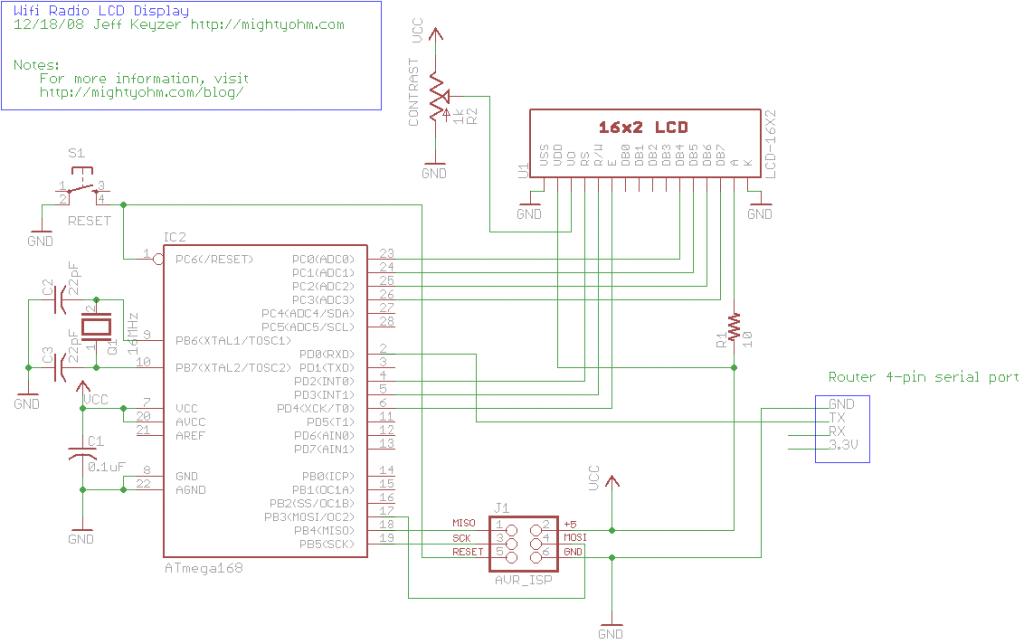
Firmware:
You can download the source code and compiled .hex file here.
Special thanks to Peter Fleury for his excellent LCD library, which saved me from reinventing the wheel! He also has another page about interfacing LCD displays to an AVR.
For more detail: Building a Wifi Radio – Part 7, Building an LCD Display