Introduction
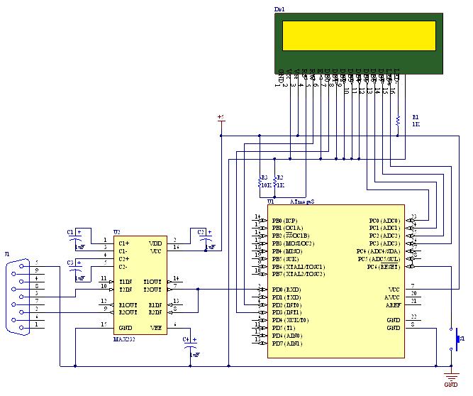
USART is one of the primitive inter-device communication protocols. It is not used in modern computers. But still, a few mother boards come with the module necessary for an USART communication. Here, in the case of PCs, the port is known as COM port and it follows RS232 protocol. It is no different from USART except for the voltage levels and some additional signals. Commonly MAX232 IC is used to translate the voltage level. MAX232 is a simple voltage translator buffer that converts +12/-12V of RS232 to 5/0V for USART. Other specifications are similar for USART and RS232. To know more about USART read this article from Wikipedia.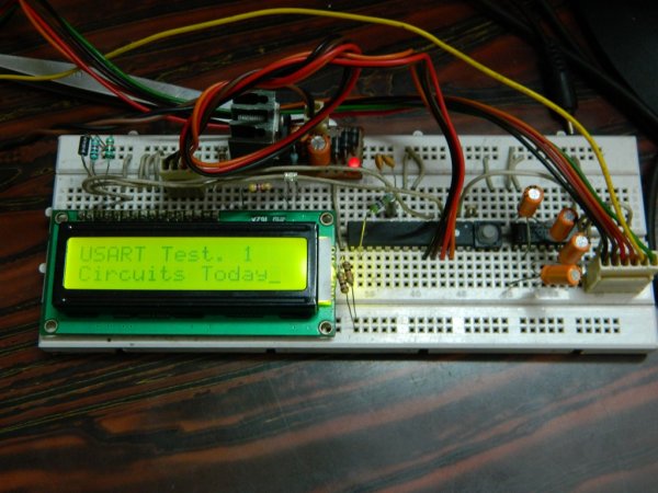
USART module in ATmega8
USART means Universal Synchronous Asynchronous Transmitter and Receiver. USART communication has provisions for full duplex communication, i.e. simultaneous transmission and reception. Synchronous means that a single clock source would be shared by end devices to facilitate communication. Asynchronous means, there would be no synchronized clock source b/w the end devices. But to receive a serial incoming data there is always a need for sampling. In addition to that, the symbol rate (i.e. the baud rate) should be known. That’s why each USART or UART module has an internal baud rate generator module. In earlier micro controllers, no separate baud rate generation unit was there. They used one of the internal timer counter for baud rate generation.
The frame (i.e. number of bits in each transmission) can consist of 5,6,7,8 or 9 data bits. Start bit starts the data transmission. There is one/two stop bit also included. There may be an even/odd parity bit included or there may not be any parity bits. The USART data register (Known as UDR for AVR micro controllers) is a double buffer register. It consists of transmitter buffer and receiver buffer. Both of them share the same I/O address. But when Data written to UDR, the data is saved to the transmitter buffer and serially shifted out from the TXD pin. And when UDR is read, the content in the receiver buffer is read which stores the serial incoming bits from the RXD pins.
Minimal settings to enable USART in ATmega8
USART module in ATmega8 have got 5 registers (4 8-bit, 1-16bit) associated with it. They are
- 1. UCSRA : USART Control and Status Register A. In this Register, three Bits indicates the status of transmission and reception. Only two bits are enough for basic programming. These are:
a) TXC- Transmission Complete
b) RXC- Reception Complete
These bits are checked before reading or writing data to UDR (USART Data Register)
- 2. UCSRB : Control and Status Register B. This register is very important to enable the USART Transmitter and Receiver. The bits associated are
a) TXEN: Transmitter Enable Bit. This enables the USART transmitter.
b) RXEN: Receiver Enable Bit. This enables the USART receiver.
- 3. UCSRC : This is the most important control register for USART. Let’s have a look.
|
USART Control and Status Register C –UCSRC |
||||||||
| Bit |
7 |
6 |
5 |
4 |
3 |
2 |
1 |
0 |
| Bit Name | URSEL | UMSEL | UPM1 | UPM0 | USBS | UCSZ1 | UCSZ0 | UCPOL |
| Read/Write |
RW |
RW |
RW |
RW |
RW |
RW |
RW |
RW |
| Initial value |
1 |
0 |
0 |
0 |
0 |
1 |
1 |
0 |
The UCSRC Register shares the same I/O location as the UBRRH Register. When doing a write access of this I/O location, the high bit of the value written, the USART Register Select (URSEL) bit, controls which one of the two registers that will be written. If URSEL is zero during a write operation, the UBRRH value will be updated. If URSEL is one, the UCSRC setting will be updated.
Bit 7 – URSEL: Register Select
This bit selects between accessing the UCSRC or the UBRRH Register. It is read as one when reading UCSRC. The URSEL must be one when writing the UCSRC.
Bit 6 – UMSEL: USART Mode Select
This bit selects between Asynchronous and Synchronous mode of operation.
|
UMSEL Bit Settings |
|
|
UMSEL |
Mode |
|
0 |
Asynchronous Operation |
|
1 |
Synchronous Operation |
Bit 5:4 – UPM1:0: Parity Mode
These bits enable and set type of Parity Generation and Check. If enabled, the Transmitter will automatically generate and send the parity of the transmitted data bits within each frame. The Receiver will generate a parity value for the incoming data and compare it to the UPM0 setting. If a mismatch is detected, the PE Flag in UCSRA will be set.
|
UPM Bit Settings |
||
|
UPM1 |
UPM0 |
Parity Modes |
|
0 |
0 |
Disabled |
|
0 |
1 |
Reserved |
|
1 |
0 |
Enabled, Even parity |
|
1 |
1 |
Enabled, Odd Parity |
Bit 3 – USBS: Stop Bit Select
This bit selects the number of stop bits to be inserted by the Transmitter. The Receiver ignores this setting.
|
USBS Bit Settings |
|
|
USBS |
Stop Bit(s) |
|
0 |
1-Bit |
|
1 |
2-Bit |
Bit 2:1 – UCSZ1:0: Character Size
The UCSZ1:0 bits combined with the UCSZ2 bit in UCSRB sets the number of data bits (Character Size) in a frame the Receiver and Transmitter use.
|
UPM Bit Settings |
|||
|
UCSZ2* |
UCSZ |
UCSZ |
Character Size |
|
0 |
0 |
0 |
5-Bit |
|
0 |
0 |
1 |
6-Bit |
|
0 |
1 |
0 |
7-Bit |
|
0 |
1 |
1 |
8-Bit |
|
1 |
0 |
0 |
Reserved |
|
1 |
0 |
1 |
Reserved |
|
1 |
1 |
0 |
Reserved |
|
1 |
1 |
1 |
9-Bit |
| *UCSZ2 Belongs to UCSRB | |||
- 4. UBRR: As mentioned earlier, writing information to UBRR is tricky. Whether we write the data to UBRRH and UCSRC, The same I/O location is used. The only thing makes the destiny differ is the MSB of the data to be written. If the MSB of the data byte is 1, Then the destiny is UCSRC, Else It is destined to be written at UBRRH. And, the Address of the UBRRL is not adjacent to UBRRH. So, although the combination of UBRRL and UBRRH is of 16bits, we cannot write a 16bit data (Like an integer variable) directly to the UBRR register. We need to write the Higher byte to the UBRRH and strip off the MSB from it before writing. And we would have to write the Low byte separately.
- UDR : The UDR is the storage of the data during the transmission or reception of the data. It is a double buffered register. So it can support a full duplex transmission. Here is what I found In Atmel’s ATmega8 datasheet:
|
USART Data Register–UDR |
||||||||
| Bit |
7 |
6 |
5 |
4 |
3 |
2 |
1 |
0 |
| UDR (Read) |
RXB[7:0] |
|||||||
| UDR (Write) |
TXB[7:0] |
|||||||
| Read/Write |
RW |
RW |
RW |
RW |
RW |
RW |
RW |
RW |
| Initial value |
1 |
0 |
0 |
0 |
0 |
1 |
1 |
0 |
The USART Transmit Data Buffer Register and USART Receive Data Buffer Registers share the same I/O address referred to as USART Data Register or UDR. The Transmit Data Buffer Register (TXB) will be the destination for data written to the UDR Register location. Reading the UDR Register location will return the contents of the Receive Data Buffer Register (RXB). For 5-bit, 6-bit, or 7-bit characters the upper unused bits will be ignored by the Transmitter and set to zero by the Receiver.
The transmit buffer can only be written when the UDRE Flag in the UCSRA Register is set. Data written to UDR when the UDRE Flag is not set, will be ignored by the USART Transmitter. When data is written to the transmit buffer (with the Transmitter being enabled) then the transmitter will load the data into the Transmit Shift Register, when the Shift Register is empty. Then the data will be serially transmitted to the TxD pin.
The receive buffer consists of a two level FIFO. The FIFO will change its state whenever the receive buffer is accessed. Due to this behavior of the receive buffer do not use Read-Modify- Write instructions (SBI and CBI) at this location. Be careful when using bit test instructions (SBIC and SBIS), since these also will change the state of the FIFO.
The target settings for this experiment are:
- a. Both transmission and reception will be enabled.
- b. There would be 8 data bits
- c. There would be 2 stop bits
- d. There would be no parity bits
- e. The transmission would be asynchronous
- f. The baud rate for the transmission would be 1200 baud
- g. The UBRR value for the baud rate is calculated as per the formula given in the datasheets. The formula is
 For more detail: How to Establish A PC-Micro controller USART communication