Introduction
This project implements rock-paper-scissors game that displays on the TV screen using camera to capture human gesture and doing image processing.
Rock-paper-scissors-spock-lizard game is very popular among teenagers. Our idea comes from a very popular American comedy: Big Bang! In this TV show we always see Sheldon playing this game with his friends. The purpose of this project is to let human play this game with computer’s random variable gestures. There are totally five different gestures included and every gesture can win two of them and lose to the other two. Figure 1 tells us about the basic rule of this game:

In order to achieve our goal, we use the digit camera OV7670 to get human gestures and then use microcontroller to send the image data to Matlab to do image processing, which can reduce the processing time. Finally we resend the results to another microcontroller which can display the game on a TV screen with computer random variable gesture. The hardest part in our project is the data transmission among camera, microcontroller and Matlab because there are some limitations in crystal frequency and Baud rate.
Also, the image processing algorithm should be efficient and accurate enough so that we can distinguish the gestures correctly. Last but not least, in the second microcontroller which is used to TV control we cannot use any ISRs because of the TV display. Then the problem we need to solve is to make sure this microcontroller can receive the result signal on time, otherwise there might be some problems which will be discussed later.
High level design
As is introduced above, this game is quite popular among teenagers, especially when they want to make some simple decisions. Actually we were hesitate to doing this project at the very beginning because the camera is hard to debug and we are not sure whether we can get enough speed, let alone we only have 8 MHz crystal frequency because the camera can only work in 3.3 Volts. But we finally decided to do this project just because we want to take challenges and we think about several tricks to speed up the data transmission.
In order to achieve our goal, there are three components required: First is the camera OV7670, this is a digital camera with 3.3V operating voltage. And we need this camera to get real-time human gestures. Then we also need a voltage transfer module on our self-build microcontroller board to get this 3.3 Volts VCC. The last main part in our project is the LCD TV because we need to display both human gesture and computer random gesture on its screen. Additionally, we need a serial port line to communicate with Matlab.
There are totally six steps. First: MCU1 tells the camera to capture image; Second: The camera sends what it gets to MCU1; Third: MCU1 sends such data to Matlab to do image processing to distinguish gestures; Fourth: Matlab tells MCU1 the processing result; Fifth: MCU1 sends the result to MCU2 to display; Sixth: MCU2 displays the result on TV and tells MCU1 that it receives the result.
In this project, we have made several tradeoff decisions between hardware and software and all this tradeoff decisions make the whole procedure faster and more efficient.
1) First of all, as the limitation of baud rate and crystal frequency on hardware, if we sent every pixel we got from the camera, the transmission time may be too long. So what we can do was to improve the transmission method on software. We first decided to send one pixel in four pixels, which no doubt could decrease the number of data. Then we did the binarization to every pixel in the microcontroller and combined every eight pixels into one byte to send. In this way we almost increased eight times of the speed.
What we did next was to compress the image we wanted to send, which meant we only recorded how many “0”s and how many “1”s according to the order. So if there were successive “0” or “1”, we just needed to send the number of it without sending several times, and this method has been called as run-length coding. These few steps above just helped us to increase the transmission speed to an acceptable one.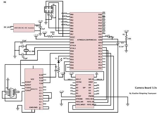
2) Then we also did a tradeoff between the total budget and crystal performance. Since the working voltage for the camera is 3.3Vand if we just bought a level shifter chip, it would cost us more budget. So we just bought the LM2596 adj module instead of LM340 which could be added to the microcontroller to let it output 3.3V VCC. But in this way we can only use 8 MHz crystal frequency rather than 16 MHz, which may decrease the baud rate of the microcontroller.
3) Another tradeoff we made is to use INT1 in MCU1 controlled by MCU2 to reset the signal flag when MCU2 received the gesture signal from MCU1. When MCU1 received the gesture information from Matlab, it will set a flag to tell MCU2 which gesture it is. However, because MCU2 was used to control the TV display, it had its own working period and maybe cannot received the signal from MCU1. So what we did was just to let MCU1 wait until MCU2 received the signal, otherwise MCU2 may not be able to receive the signal or receive something wrong.
Standards in use
Four basic standards are used in our design, including camera configuration protocol SCCB, Video Graphics Array protocol VGA, serial communication protocol rs-232, and an analog TV display protocol NTSC.
SCCB is known as serial camera control bus. It is designed by the company OmniVision as a standard to configure the register inside the camera. It is quite similar to the standard IIC protocol, which is described in the webpage below. In detailed design part we will explain the timing issue of SCCB and describe how to implement it software.
http://en.wikipedia.org/wiki/I%C2%B2C
VGA is a widely used graphical standard, it support 640*480 video mode at a refreshing rate of 60 fps.
n our camera module, horizontal sync signal is named HREF, and vertical Sync signal is named Vsync. PCLK is the pixel clock and so every rising edge of PCLK we can read a pixel from data port. In our camera module, we have 16 bits data port, 8 bit for gray scale data, and 8 bit for hue information.
General timing issues are shown in the table below. To know more about VGA standard, you can visit http://en.wikipedia.org/wiki/Video_Graphics_Array for detailed information.
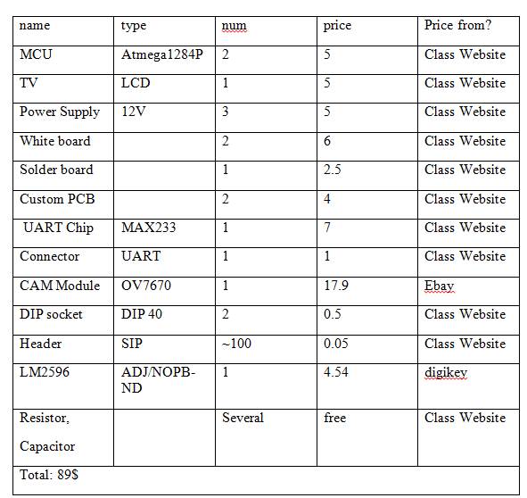
Parts List:
For more detail: Rock-Paper-Scissors-Spock-Lizard Game Using Atmega1284