Summary of 3D gForce Mouse Using Mega32
This article details the creation of a 3D gForce Mouse, a zero-impact pointing device designed to assist users with injuries. The project utilizes an ADXL202 accelerometer to detect tilt and movement, processed by an Atmel Mega32 MCU on an STK500 protoboard. The system converts analog signals into PS/2 protocol data packets to control cursor movement and scrolling on a computer. The casing is uniquely crafted from a coconut shell, featuring push buttons for clicking functionality.
Parts used in the 3D gForce Mouse:
- Analog ADXL202JE
- PCB board for mounting ADXL202JE
- Atmel Mega32 MCU
- STK500 Protoboard
- PS/2 cable
- Push buttons
- Coconut shell for mouse casing
- ProtoBoard
Introduction
“Our 3D gForce Mouse will enable use to move the curser in the air freely with the capacity of scrolling”
The rationale for this design is two fold. We wanted to do this design because we wanted to make a zero-impact pointing device for those with injury. We also wanted to implement this injury conscious device for its business opportunities.

We are using the 2-axis ADXL202 accelerometer to measure acclecration and tilt to operate the mouse. We measure the analog output signal and perform A/D conversion on the Mega32 MCU and the STK500 protoboard. Then the MCU generates serial signal packets on STK500 output pins to drive the computer mouse according to the PS/2 standard protocal. This mouse will perform horizontal and vertical movements in addition to scrolling. We will simulate clicking of the mouse buttons by having push buttons on our design breadboard. We origionally designed mouse to calcuate displacement in space due to 3-D acceleration. However we found out that the accelerometer is more accurate in measuring tilt than measuring short pulses of movement. Also, we had to work with the PS/2 protocal because we wanted to implement the scrolling function with our mouse.
Making the PS/2 protocal function is the biggest challenge of our project. The PS/2 protocal is a two way serial transmittion protocal, where the computer (or host) can request to send information to the device. There are no “official” documentation on the PS/2 protocal, but there is execellent information on http://govschl.ndsu.nodak.edu/~achapwes/PICmicro/
High Level Design
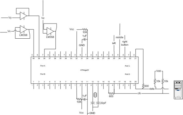
The hardware design block diagram of our gMouse will be as follows
The MCU will generate output signals according to the PS/2 standard protocol. There are two output pins, the first one is DATA, and the second one is CLOCK. In the PS/2 protocol, the device will drive the CLOCK signal. Both the CLOCK and DATA will float default at VCC. During transmission, the mouse will drive the CLOCK and DATA lines. The PS/2 protocol requires the device to send clock between about 10 kHz to 16 kHz. In our specific implementation, our clock speed is 12.50 kHz, which is about 60 microseconds per clock cycle. The host can inhibit device transmission by pulling the CLOCK signal low for more than 100 microsends. The host could pull the CLOCK signal low for two reasons: one is to inhibit transmission because the host is processing data, and the other is to request to send information to the mouse. In the second case the host will pull the DATA line low to generate a start bit and wait for the device to generate the clock signal. More information on the PS/2 protocol can be found on http://govschl.ndsu.nodak.edu/~achapwes/PICmicro/.We also uses three ports on the MCU for ADC conversion. This is similar to the digital thermometer lab. We hook up the analog output from the chip, which is soldered to a PCB provided by the professor.
The software design on the MCU will be as follows:

Our software will measure the ADC input and convert it to PS/2 mouse data packets. First, we will introduce the PS/2 protocol. A PS/2 byte has 11 bits. (A) 1 start bit. This is always 0. (B) 8 data bits, least significant bit first. (C) 1 parity bit (odd parity, 1 when number of bits is even). (D) 1 stop bit. This is always 1.
On a device-to-host transmission, the keyboard/mouse writes a bit on the Data line when Clock is high, and it is read by the host when Clock is low. The host-to-device is request or transmission is a little more complicated. The host will pull the clock to ground for more than 100 microseconds, and then the host will bring the data line low to signal a start bit. Then the host will start waiting for the device to generate a clock signal, the host will send bits of data to the device based on the device generated clock. The device should expect to receive the initial start bit, 8 data bits, a parity bit, and a stop bit. The data bits are valid for the device to read when the clock is high. The device is also expected to generate an ACK bit back to the host after receiving the stop bit, and the host should be able to read the ACK bit when the clock is low. There will be more detailed information on how we implemented the PS/2 protocol in the program design section.
Hardware Design
This is our hardware design for the mouse. We uses a palm-sized coconut shell for the mouse casing. We have considered other casing possibility for usability testing. We first used an plastic egg shaped container that is about the size of an egg, however we consider it too small and the cutting of plastic is unpleasent to the user.
Our mouse also have push buttons that serve as the click buttons for the mouse. It is mounted on the front of the coconut shell. The user will be comfortably able to click the mouse buttons.
We uses the Analog Device ADXL202 accelerometer for sensing the mouse motion. The ADXL202JE chip layout is as follows:
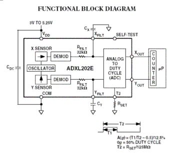
The ADXL202 has both digital and analog outputs. We will mainly use the analog output since the Atmel Mega32 has 8 available slots to receive analog inputs for A/D conversion. The capacitor Cy determines the bandwidth of the analog output. The Xout is the analog output for the x-axis acceleration, and Yout is the analog ouptut for the y-axis acceleration. The ADXL202 chip is also capable of generating digital signal, by using a pulse modulated duty cycle. The Rset resistor value will set the proportion of the data versus the period of the duty cycle.
Since our mouse is based on tilt, the cursor will move when the mouse is tilted, within some histerysis factor. This means there is a grace degree, and within that degree from being flat the mouse will stop moving.
Our ADC circuit is similar to previous labs. We connect the ADC to port A on the STK500 board. We uses port C for the push buttons. We may eventually build an standalone design, however that will only be done if we have extra time.
We also amplify the analog output signal by using an op-amp. The Op-Amps used is the LM358 (lower power dual Op-Amps) from National Semiconductor. The Op-Amp is used for impedance matching in order for the signal to be strong enough for reading.
Program Design
We spent much time getting the PS/2 communication protocol working. Our MCU is able to generate data and clock signals for it to be recognized by the computer boot up sequence. After the BIOS boot up, Windows (or other operating systems) is able to detect our mouse and show it on the screen. We are also able to send movement byte packets to the computer that represents movement and clicking of the mouse. Upon boot up sequence, we also were able to identify ourselves as a Microsoft scrolling mouse and were able to send a four-byte movement packet including the scrolling data byte. The Microsoft scrolling mouse send movement packets of four bytes, whereas the normal PS/2 mouse sends movement packets of three bytes.
We followed closely to the PS/2 communication protocal by following the information given on Adam Chapweske’s page. We also used Joseph Weaver and Rob Buels’s host emulator to test our mouse software design. We used the AVR protoboard with the 90s8515 chip for the host emulator. We also intercepted signal from a real Mircosoft’s scrolling mouse to follow the delay between bytes and packets exactly.
We used a state machine for transmitting and receiving mouse packets. There are four states in the state machine. First is an IDLE state. In the IDLE state the outputs will float high if the mouse is not sending anything. If the mouse has anything to send, it will go to the BUSY state. Depending on weather the mouse is sending packets to the host or receiving the packets from the host, it will set corresponding output flags ‘transmitting’ or ‘receiving’. The PS/2 communication is two-way, and the host can inhibit mouse’s activity by pulling the clock signal to low for more than 100 microseconds. Since the clock period of the mouse is 80 microsends, the mouse can check if the host has been trying to inhibit communication by checking if the mouse is outputting high clock but is actually reading a low from the clock because the host is pulling it low. Our clock frequency is 12.5 kHz, which is acceptable for a PS/2 protocol which requires frequency from 10 kHz to 16 kHz. After the mouse sees the host inhibits for more than 100 microseconds, it the state machine will transition into the INHIBIT state, stop all transmission and float both clock and data to 1. Note however, if the host inhibits transmission before the mouse finishes sending a byte (bit 10 of the byte), the mouse will prepare to resend that byte again whenever possible. The host can request to send information to the mouse by pulling the data line low after he pulls the clock line low for more than 100 microseconds. This makes the state machine to transition into the REQUEST state. By the next clock cycle the state machine will transition into BUSY state with output ‘receiving’ equals to 1. When the host pull the data line low this is a signal for start bit for the mouse, and the mouse should start generate clock signals by first making clock to high. The host will then send the 11 bit data when the clock is low, and the data becomes valid when the clock is high and then the mouse can check the data when the clock is high. After receiving the stop bit from the host the mouse will send an ACK bit to the host when the clock is high and the host will read that ACK bit when the clock is low.Please refer to Adam Chapweske’s page for more information.
It is important to note that in a digital design with clock signals such as the PS/2 mouse we need to be careful about the states and the signals and should avoid hazards. This means that all state machines should be driven by the same clock and we should avoid clock skews. Failure to do so will result in unpredictable behavior for both the state machine and the signals. In our design found out that we should only change the state and the output when timer 1 interrupts for the signals to be synchronous. We spent much time trying to debug our digital design and signals and were finally able to get our mouse recognized by the BIOS and Windows.
| Parts | # | Cost |
| Analog ADXL202JE | 2 | $0 (Free samples from Analog.com) |
| PCB board for mounting ADXL202JE | 2 | $0 (Thanks to Professor Land for the board and soldering!) |
| Atmel Mega32 MCU | 1 | $8 |
| STK500 Protoboard | 1 | $0 (Available from the lab) |
| PS/2 cable | 1 | $0 (Home Made from a USB to PS/2 converter) |
| Push buttons | 1 | $0 (From Lab) |
| Coconut shell for mouse casing | 1 | $0 (From some coconut ice cream that Eric ate last summer!) |
| ProtoBoard | 1 | $2.5 |
| Total: | $10.5 | |
For more detail: 3D gForce Mouse Using Mega32
- How does the mouse measure motion?
The mouse uses a 2-axis ADXL202 accelerometer to measure acceleration and tilt rather than short pulses of movement. - What protocol does the mouse use to communicate with the computer?
The mouse generates serial signal packets according to the PS/2 standard protocol. - Can this mouse perform scrolling functions?
Yes, the design identifies as a Microsoft scrolling mouse and sends four-byte movement packets including scrolling data. - Why was the ADXL202 chosen over other sensors?
The team found the accelerometer more accurate in measuring tilt than measuring short pulses of movement. - What component is used to amplify the analog output signal?
An LM358 Op-Amp is used for impedance matching to ensure the signal is strong enough for reading. - How many states are in the software state machine?
There are four states in the state machine: IDLE, BUSY, INHIBIT, and REQUEST. - What is the clock speed used in the specific implementation?
The clock speed is 12.50 kHz, which falls within the required range of 10 kHz to 16 kHz for the PS/2 protocol. - What material was used for the mouse casing?
A palm-sized coconut shell was used for the casing because plastic alternatives were considered too small or unpleasant to cut.