
Summary of 3D-Printed RGB Wallet
This article details a DIY project to build an ostentatious 3D-printed RGB wallet featuring customizable name engraving, integrated lighting, and compact electronics. The build involves printing the wallet components using Fusion or STL files, then assembling a free-wired circuit containing NeoPixels, an ATtiny microcontroller, and a small battery within the base compartment. The guide covers soldering techniques, software uploading via Arduino, and assembly tips for optimal light diffusion.
Parts used in the 3D-Printed RGB Wallet:
- 3D printer with PLA or ABS filament
- Fusion archive file or STL files
- Three button-size NeoPixels
- ATtiny microcontroller (specifically ATtiny85)
- DIP socket
- 100 mAh battery
- JST connector
- Wires and solder
- Hot glue for strain relief
Stand out from the crowd with this unabashedly ostentatious excuse for a wallet. It’s got plenty of space, RGB lights, and you can even put your name on it for added vanity. Interested? Keep reading! In the files section of this build you can find two things: a Fusion archive and some STL files. If you’re just interested in printing a blank wallet without any text on it then download the STL files. Load them into your favorite 3D-print utility, and make sure they’re in the orientation shown above. No rafts or support material are necessary, and anywhere from 0.3mm per layer to 0.05mm per layer should work. If you would like to customize the design, import the archive into Fusion and get to work! If you want a customized design but don’t want to put any effort in, message me and I can help you out.
The challenge here is getting three NeoPixels, a microcontroller, and a battery to fit in the tiny base compartment of the wallet. The parts I chose reflect the small space: button-size NeoPixels, an ATtiny, and a 100 mAh battery. There’s also no space for a printed circuit board, breadboard, or perfboard; the only remaining option is to free-wire the circuit! Free-wiring is a technique where you utilize only wires and solder to connect everything together. If you’ve never done it before, this is an easy project to start on!
The first component to start on is the NeoPixels. Use the base of the wallet as a template and try to put an equal amount of wire in between each NeoPixel. Also leave a fair bit of wire on the end to connect to the microcontroller. See the above image if you get stuck. Also, be sure to wire the data bus on the NeoPixels in the direction indicated: out to in only!
After pretty much every connection you solder it’s important to place a dab of hot glue for strain relief. Rather than having all the stress on a solder joint you can offload some of that stress onto the board and the wire’s coating. This helps prevent connections from snapping.
Step 5: JST Connector
Solder a small piece of wire onto each terminal of the JST connector, and be sure to identify which one is positive and which is ground.
Step 6: Connecting Everything Together
You will need to solder the ground of the JST connector and the ground of the NeoPixel strip to pin four of the DIP socket, then solder the positive of each to the opposite corner of the DIP socket (pin 8). The data line on the NeoPixels should go to pin 2 on the DIP socket, or output three of the ATtiny. Be sure to leave an ample amount of wire so you have the ability to move components around to get them to fit in the base.
Step 7: Uploading the Software
I created an electronics lab simulation so you can test out software before you upload it to the ATtiny. Check it out here: https://circuits.io/circuits/4882007-3d-printed-rgb-wallet-circuit. The demo sketch attached in the code section of this build uses functions taken from the Adafruit NeoPixel library. It cycles through various colors on each NeoPixel, producing a cool multi-colored effect. Upload that sketch to the ATtiny by following the instructions in this tutorial: https://create.arduino.cc/projecthub/arjun/programming-attiny85-with-arduino-uno-afb829.
If you’ve done this before and know how to program an ATtiny85 just make sure you burn the bootloader first. I spent the better part of an hour trying to debug my circuit because the lights weren’t behaving correctly only to discover that burning the bootloader could fix it.
Step 8: Smooshing It All in There
Plug the ATtiny85 into the DIP socket (in the correct orientation!) and the lights should start changing colors. You can now place the whole circuit into the base of the wallet as shown, then snap the base onto the middle section. The lights should diffuse nicely throughout the whole thing. I recommend white PLA or ABS for the best effect.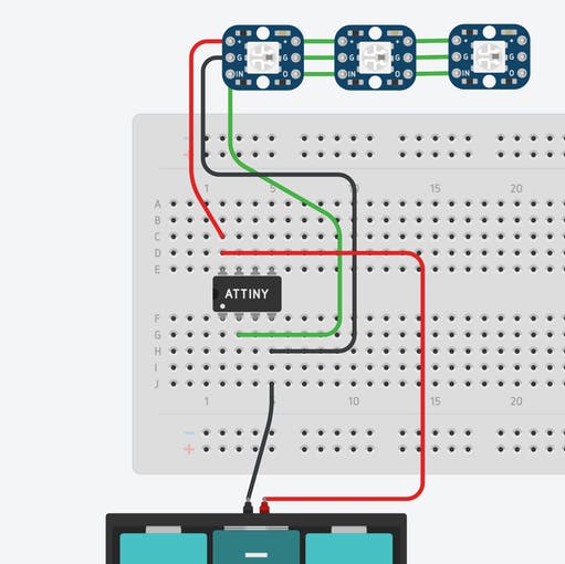
More Information
The wallet itself can actually fit more than it appears. There’s room for four credit cards in the middle section, a bunch of bills, and coins of all different sizes. You can remove the base with the lights whenever you want to make the wallet even smaller. NeoPixels are pretty power hungry. Given the small size of the battery the circuit can run for a little over an hour. Keep this in mind when showing off your creation!
For more detail: 3D-Printed RGB Wallet
-
What files are needed to print the wallet?
You can download a Fusion archive for customization or STL files for a blank design. -
Do I need support material when 3D printing this wallet?
No rafts or support material are necessary for printing the wallet parts. -
How should the NeoPixel data bus be wired?
The data bus must be wired in the direction indicated from out to in only. -
Why is hot glue applied after soldering connections?
Hot glue provides strain relief to prevent connections from snapping by offloading stress. -
Can I test the software before uploading it to the microcontroller?
Yes, you can use an electronics lab simulation link provided to test the software first. -
What library functions are used in the demo sketch?
The demo sketch uses functions taken from the Adafruit NeoPixel library. -
What happens if the lights do not behave correctly after uploading code?
Burning the bootloader on the ATtiny85 might fix the issue if the lights are not behaving correctly. -
How long does the battery last during operation?
The circuit can run for a little over an hour given the small size of the battery. -
Which filament color is recommended for the best light effect?
White PLA or ABS is recommended for the best light diffusion effect.
