
Summary of 8051 ROBOT ARM STEPPER MOTOR CONTROL
This article details an 8051 microcontroller-based robot arm project utilizing three stepper motors for movement. The design employs half-step mode with a specific winding code sequence ({1, 3, 2, 6, 4, 12, 8, 9}) to control the joints. Directional control is achieved via buttons, and the ULN2003A integrated circuit is used to drive the motors. The project includes schematic diagrams, PCB layouts, source code, and Proteus ISIS simulation files available for download.
Parts used in the 8051 Robot ARM:
- 8051 Microcontroller
- Three Stepper Motors
- ULN2003A Integrated Circuit
- Control Buttons
- Schematic Diagrams
- PCB Layouts
- Source Code
- Proteus ISIS Simulation Files
In this 8051 Robot ARM application I use for robot arm 3 stepper motor design, study and is to be informed about the expulsion. Stepping motors to provide work, applied to the ends of… Electronics Projects, 8051 Robot ARM Stepper Motor Control “avr project, microcontroller projects, “
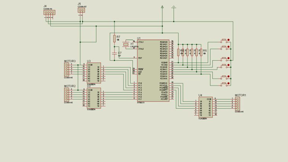
In this 8051 Robot ARM application I use for robot arm 3 stepper motor design. Study and is to be informed about the expulsion. Stepping motors to provide work, applied to the ends of the half step mode and winding {1, 3, 2, 6, 4, 12, 8, 9} code sequence used. The last of the stepper motor has been used integrated ULN2003A. To determine the direction of movement of the Robot arm buttons are used. On the next page I wrote program robot arm step motors (joints) continues its move at the same time.
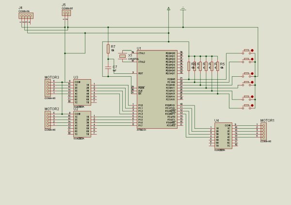
8051 ROBOT ARM SCHEMATIC
8051 ROBOT ARM PCB
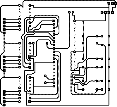
source code: 8051 ROBOT ARM STEPPER MOTOR CONTROL proteus isis simulation pcb files: 8051-robot-arm-stepper-motor-control.rar
- How many stepper motors are used in this robot arm design?
The design uses three stepper motors. - What mode is applied to the stepping motors?
The motors are applied to the ends of the half step mode. - Which winding code sequence is used for the motors?
The sequence {1, 3, 2, 6, 4, 12, 8, 9} is used. - What component determines the direction of movement?
Buttons are used to determine the direction of movement of the robot arm. - Which integrated circuit is used at the end of the stepper motor?
The ULN2003A integrated circuit is used. - Can I obtain the source code for this project?
Yes, the source code is provided in the download file. - Is there a simulation available for this design?
Yes, Proteus ISIS simulation files are included. - Does the program allow simultaneous movement of joints?
Yes, the program allows step motors (joints) to continue moving at the same time.
