
Summary of Burn Arduino Bootloader on Atmega-328 TQFP and DIP chips on Breadboard
This article guides users through building a custom setup to burn bootloaders onto Atmega328 chips using an Arduino Uno as an ISP programmer. It details the necessary hardware components, software prerequisites, and specific configuration steps for avrdude. The process involves uploading the ArduinoISP sketch, wiring components on a breadboard, and modifying system files to support specific chip signatures before programming.
Parts used in the Custom Bootloader Burner Project:
- Arduino Uno Board
- TQFP 32 to DIP 28 Adapter
- Atmega TQFP 32 pin chip
- Atmega DIP 28 pin chip
- 10K resistor
- 16MHz crystal
- 18pf - 22pf capacitor (2)
- Tact Switch
- Jumper wires
- LED
- 560 Ohm resistor
- 10uF electrolytic cap
- Breadboard
- Arduino Pins (2x6 pins, 2x8 pin socket)
- ZIF socket 28 pin
- Arduino Uno Board (1)
- TQFP 32 to DIP 28 Adapter (1) Link
- Atmega TQFP 32 pin chip (1)
- Atmega DIP 28 pin chip (1)
- 10K resistor (1)
- 16MHz crystal (1)
- 18pf – 22pf capacitor (2)
- Tact Switch (1)
- Jumper wires (few)
- LED (1)
- 560 Ohm resistor (1)
- 10uF electrolytic cap (optional)
- Breadboard (1)
- Arduino Pins (2×6 pins, 2×8 pin socket)
- ZIF socket 28 pin (1)
Software pre-requisites : Arduino software installed
If you like this Instructable. I greatly appreciate your Vote for this Instructable @ http://www.instructables.com/contest/123dcircuits…
Thank You
Step 1: Burn Arduino ISP to Arduino board
Connect Arduino Uno board to your computer. Start Arduino program and from examples choose “ArduinoISP” sketch and upload it to “Arduino Uno” board. Please make sure you select the correct board name and serial port. Now this board is ready to program new Atmega-328 chips on the breadboard as shown in the next step.
Step 2: Arrange all components on breadboard
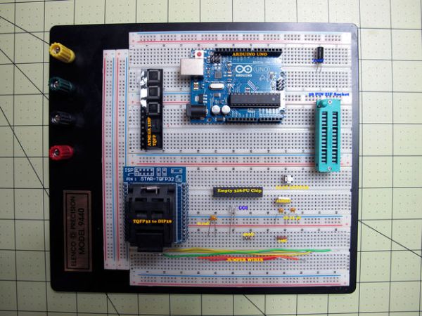
Wire all components as shown in this picture on the breadboard. The Ziff socket is placed starting on pin 21, Add markings on the Breadboard to show Pin 1, Pin 14, Pin 15, Pin 28 of Atmega dip28 chip as it will be easy to wire later. The Breadboard does not show power, But run power +5V and GND from breadboard to Arduino board.
Wire all components as shown in this picture on the breadboard. The Ziff socket is placed starting on pin 21, Add markings on the Breadboard to show Pin 1, Pin 14, Pin 15, Pin 28 of Atmega dip28 chip as it will be easy to wire later. The Breadboard does not show power, But run power +5V and GND from breadboard to Arduino board.
Step 3: Update Signature inside avrdude conf file
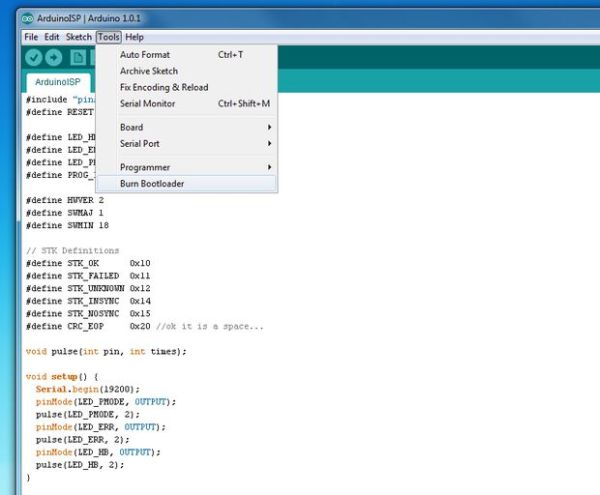
Please make a backup of avrdude file and copy it so original file is left untouched and you can fail back to it if required. This file can be found under “C:\arduino-1.0.1\hardware\tools\avr\etc\avrdude”.
Please restart Arduino program after you update “avrdude” config file.
The “#” sign in from of the signature indicates comment (not used by arduino)
For more detail: Burn Arduino Bootloader on Atmega-328 TQFP and DIP chips on Breadboard
- How do I prepare the Arduino board for programming?
Upload the ArduinoISP sketch from examples to the Arduino Uno board via the Arduino program. - Where should the Ziff socket be placed on the breadboard?
The Ziff socket is placed starting on pin 21 of the breadboard. - Which pins need markings on the breadboard?
Add markings to show Pin 1, Pin 14, Pin 15, and Pin 28 of the Atmega dip28 chip. - How do I connect power to the breadboard?
Run power +5V and GND from the breadboard to the Arduino board. - Why might I need to update the avrdude conf file?
You may need to update it to test burning a bootloader on specific Atmega 328 DIP-28 chips like the Atmega 328-PU. - What is the recommended path for the avrdude config file?
The file can be found under C:arduino-1.0.1hardwaretoolsavretcavrdude. - Should I modify the original avrdude file directly?
No, make a backup copy first so the original file remains untouched. - What must I do after updating the avrdude config file?
Restart the Arduino program after you update the avrdude config file.
