
Summary of Relais Driver Board
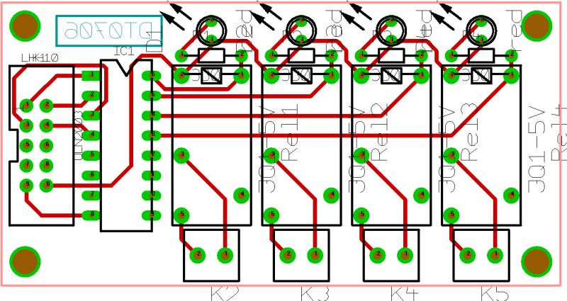
This article describes a 4-relay peripheral board designed for the AT2313 Project. The board features an ML10 output connector, four LEDs with current-limiting resistors for status indication, and four 2-pole screw connectors for load connections. Its core component is the ULN2803A IC, which amplifies microcontroller signals using built-in protection diodes, eliminating the need for external components.
Parts used in the Relais Driver Board:
- ML10 output connector
- ULN2803A IC
- Four LED's
- Current limiting resistors
- Four 2-pole screw connectors
This is a peripheral board with 4 relais, rated at 5A/250V each. The board has a ML10 output connector for connection with the AT2313 Project board. It has also 4 LED’s for indication which relais is switched on.
Hardware
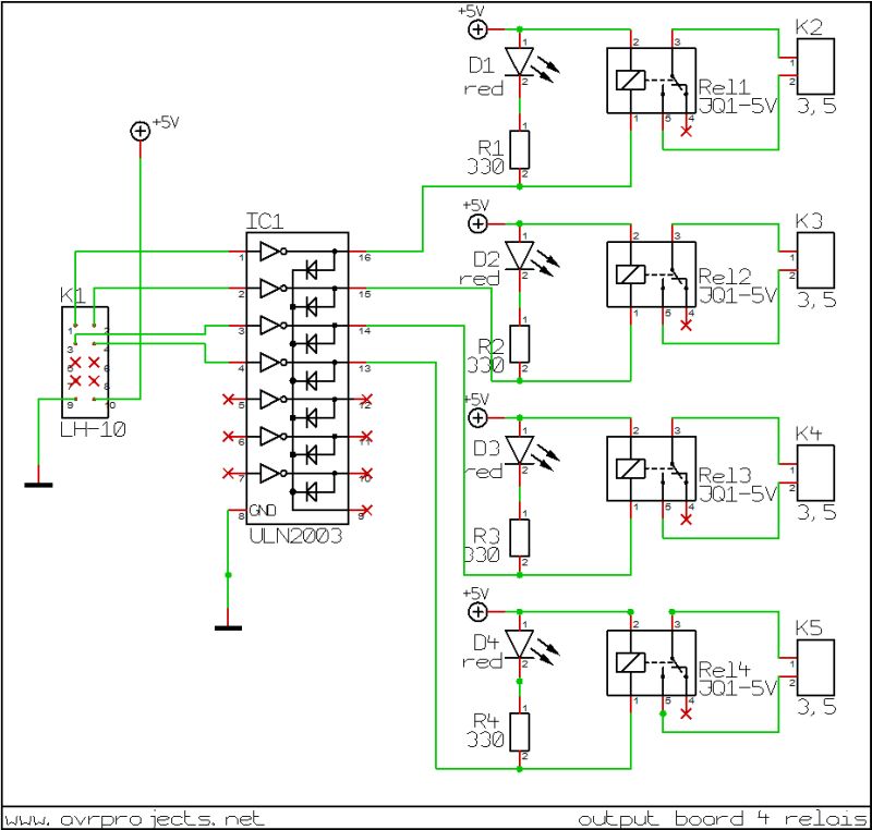
The circuit is simple, it consists of no more then an ML10 connector, a ULN2803A, which contains eight open collector darlington transistors, four of them amplifies the signals that come from the microcontroller. The IC has build in protection diodes, so no external diodes for driving the relais are needed. There are also four LED’s with current limiting resistors to indicate if a relais is energized, each output of the relais goes to a 2-pole screw connector.
Schematic Circuit and PCB Layout
Below you see the picture of the curcuit
For more detail: Relais Driver Board
-
What is the primary function of the ULN2803A in this circuit?
The ULN2803A contains eight open collector darlington transistors where four amplify signals from the microcontroller. -
How does the board indicate if a relay is energized?
It uses four LED's with current limiting resistors to provide visual indication. -
Are external diodes required to drive the relays?
No, the IC has built-in protection diodes so no external diodes are needed. -
What type of connectors connect the relay outputs to the load?
Each output goes to a 2-pole screw connector. -
Which project board does this peripheral board connect to via the ML10 connector?
It connects with the AT2313 Project board. -
What are the electrical ratings for each relay on the board?
Each relay is rated at 5A/250V. -
How many relays are included on this peripheral board?
The board includes four relays.
