
Summary of Temperature indicator
This project describes a digital thermostat using a Dallas DS1621 temperature sensor and an ATMEGA ATTiny2313 microcontroller. The system measures temperatures between -55°C and +125°C, displaying the status via three LEDs based on user-defined ranges. It features a programmable thermal alarm with hysteresis that drives a relay to control external devices like heaters or blowers. Communication occurs over a 2-wire serial interface, and the circuit operates on a 5V power supply.
Parts used in the Digital Thermostat Project:
- Dallas DS1621 temperature sensor
- ATMEL ATTiny2313 microcontroller
- BC557 PNP transistor
- Relay
- Heater element or blower fan
- Three LEDs
- Resistors
- 5V power supply (wall-wart)
This project uses a Dallas DS1621 temperature sensor which indicates the temparature of the device.
The temperature sensor has an thermal alarm output, which becomes high when the temperature of the device exceeds a user defined value. When the temperature drops below a user defined value, the alarm output becomes low. In this way any amonut of hysteresis can be programmed.
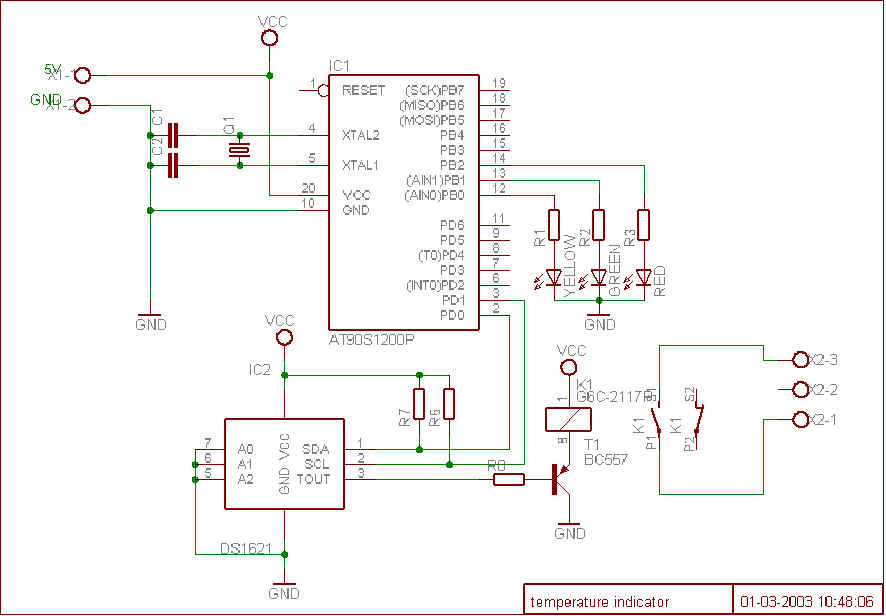
 The values are stored in a special register of the device that is nonvolatile. The signal of the alarm output is amplified by a BC557 PNP transistor, that drives a relay that can switch a heater element or a blower on or off.
The temperature settings and readings are communicated to/from the device over a simple 2-wire serial interface. An ATMEL ATTiny2313 microcontroller controls the serial communication to/from the DS1621.The microcontroller also controls three LED, only one of the LED’s is on when the temparature is within a certain range. The range of the temperature in which the LED’s are on can be set by the user in the program code. The circuit needs to be powered by a 5V power supply, which can be obtained from a wall-wart.
Features:
- Measures temperatures from -55°C to +125°C
- Three LED’s to indicate in what range the temparature is.
- User definable thermostat with high and low settings
- Output via a relay to control a heater element or a blower fan (or something else)
- Power supply ………………….4.5 to 5.5 VDC
- Power consumption ………..15mA
Circuit Schematic and PCB Layout
It contains only a few parts, a DS1621 temperature sensor, a attiny2313 micrcontroller,three LED’s one relay and some resitors. I have made a small printed circuit board for it.
For more detail: Temperature indicator
- How does the thermal alarm output work?
The alarm output becomes high when the temperature exceeds a user-defined value and low when it drops below that value. - Can the hysteresis be programmed?
Yes, any amount of hysteresis can be programmed by setting the values in the device's nonvolatile register. - What component amplifies the alarm signal?
A BC557 PNP transistor amplifies the signal of the alarm output to drive the relay. - How are temperature settings communicated?
Settings and readings are communicated to and from the device over a simple 2-wire serial interface. - What controls the serial communication?
An ATMEL ATTiny2313 microcontroller controls the serial communication to and from the DS1621. - How many LEDs are used and what do they indicate?
Three LEDs are used, and only one is on at a time to show which temperature range the current reading falls into. - Can the LED range settings be changed?
Yes, the range of temperature for the LEDs can be set by the user in the program code. - What voltage is required to power the circuit?
The circuit needs to be powered by a 5V power supply, typically obtained from a wall-wart. - What is the operating temperature range of the sensor?
The sensor measures temperatures from -55°C to +125°C.
