Summary of A Connected Lamp to Wake Me Up
This article describes a DIY project converting two IKEA lamps into an ESP8266-controlled alarm clock. The build utilizes 10W RGB LEDs and an A6211 LED driver to manage power efficiently, avoiding heat issues associated with series resistors. A DC/DC converter steps down voltage from 12V to 5V for the microcontroller, while an expansion connector allows for future accelerometer integration to track sleep cycles and optimize wake-up times using light intensity.
Parts used in Connected Lamp Alarm Clock:
- Two IKEA lamps
- 10W RGB LEDs
- ESP8266 microcontroller
- A6211 LED driver
- Shunt resistor
- Resistors R2, R3, R4
- Capacitors C13, C14, C15
- DC/DC converter
- P1 power input connector
- P3 interface connector
- P4 expansion connector
- Accelerometer (planned)
The Idea
So for some reason I bought 2 IKEA lamps at a flea market. As IKEA furniture has a long history of being hacker-friendly, I figured they shouldn’t be an exception to the rule.
My plan? Fit a few 10W RGB LEDs in there together with an ESP8266 to use the final result as an alarm clock.
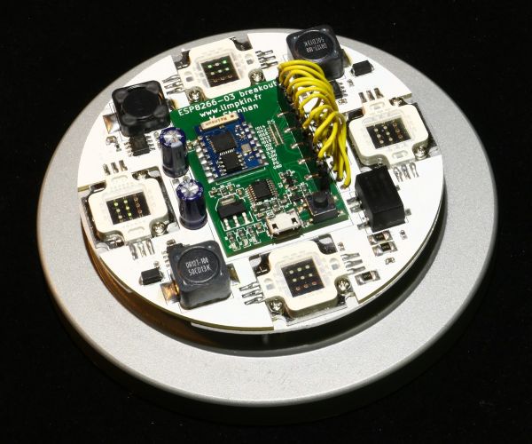
The Schematics
When you are dealing with a LED consuming that much current, you can’t simply use a series resistor as the latter would need to dissipate R*I² in heat. I’m therefore using a dedicated LED driver that automatically adjusts the LED voltage to match a given current. As you can guess, it isn’t much different than a standard step-down and just uses a shunt resistor to measure the current flowing through the LED.
The A6211 has an adjustable switching frequency set using R2/R3/R4 (to 700KHz in our case) and an EN input meant to be connected to a PWM signal. Its datasheet is well made so you can easily find all the information needed to select your passive components values. C13/C14/C15 are here to decrease the current ripple.
The complete board is 12V powered through P1. A DC/DC is placed on the board (I was lazy) to provide the 5V needed by my ESP8266 dev board. The P3 connector therefore serves as an interface beween the latter and our main PCB.
P4 is meant as an expansion connector to which will be connected an accelerometer. The goal is to hopefully measure REM sleep cycles to gradually increase the light at optimal times.
The great thing in this project is that the ESP8266 has all the required IOs for my purpose (PWM outputs, I2C, std IOs).
For more detail: A Connected Lamp to Wake Me Up
- Why is a dedicated LED driver used instead of a series resistor?
A series resistor would dissipate too much heat due to high current, so a dedicated driver automatically adjusts voltage to match the required current. - How is the switching frequency set on the A6211 driver?
The frequency is adjusted using resistors R2, R3, and R4, which are set to 700KHz in this specific design. - What is the purpose of capacitors C13, C14, and C15?
These capacitors are included to decrease the current ripple within the circuit. - How does the board provide power to the ESP8266?
A DC/DC converter on the board steps down the 12V input to 5V needed by the ESP8266 dev board. - What is the intended function of the P4 expansion connector?
The P4 connector is designed to attach an accelerometer to measure REM sleep cycles for gradual light increase. - Can the ESP8266 handle all the required inputs and outputs for this project?
Yes, the ESP8266 possesses all necessary IOs including PWM outputs, I2C, and standard IOs for this application. - What voltage powers the complete PCB through connector P1?
The complete board is powered through P1 at 12V. - Why was a DC/DC converter placed directly on the board?
The author mentions placing it on the board because they were lazy to implement an external solution.