
Summary of Joystick Interfacing with AVR Microcontroller
This tutorial explains interfacing a joystick module with an ATMEGA8 microcontroller to detect four directional movements. The system uses two ADC channels (PORTC0 and PORTC1) to read voltage changes from the joystick's horizontal and vertical potentiometers. These analog signals are converted to digital values, controlling four LEDs that indicate the stick's direction. The project utilizes Atmel Studio 6.1 for software development and an AVR-ISP programmer for hardware configuration.
Parts used in the Joystick Interfacing with AVR Microcontroller:
- ATMEGA8
- Power supply (5v)
- AVR-ISP PROGRAMMER
- LED (4 pieces)
- 1000uF capacitor
- 100nF capacitor (5 pieces)
- 1KΩ resistor (6 pieces)
- Joystick module
In this tutorial we are going to interface a joystick module with atmega8 microcontroller. A JOY STICK is an input module used for communication. It basically makes easy the user machine communication. A joystick is shown in below figure.
The joystick module has two axis – one is horizontal and other is vertical. Each axis of joystick is mounted to a potentiometer or pot or variable resistance. The mid points are brought down as Rx and Ry. These pins carry as output signal pins for JOYSTICK. When the stick is moved along horizontal axis , with the supply voltage present , the voltage at Rx pin changes.
The voltage at Rx increases when moved forward, the voltage at Rx pin decreases when moved backward. Similarly, the voltage at Ry increases when moved upward, the voltage at Ry pin decreases when moved downward.
So we have four directions of JOYSTICK on two ADC channels. At normal cases we have 1Volt on each pin under normal circumstances. When the stick is moved the voltage on each pin goes high or low depending on direction. So four directions as ( 0V,5V on channel 0) for x- axis; ( 0V,5V on channel 1) for y- axis.
We are going to use two ADC channels of ATMEGA8 to do the job. We are going to use channel 0 and channel 1.
Components Required
Hardware: ATMEGA8, power supply (5v), AVR-ISP PROGRAMMER, LED (4 pieces), 1000uF capacitor, 100nF capacitor (5 pieces), 1KΩ resistor (6 pieces).
Software: Atmel studio 6.1, progisp or flash magic.
Circuit Diagram and Working Explanation

The voltage across JOYSTICK is not completely linear; it will be a noisy one. To filter out the noise a capacitors are placed across each resistor in the circuit as shown in figure.
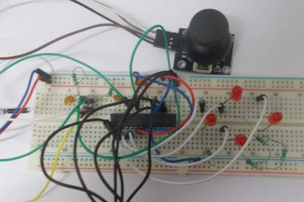
As shown in figure there are four LEDs in the circuit. Each LED represents each direction of JOYSTICK. When the stick is moved in a direction, then the corresponding LED glows.
Before going any further we need to talk about ADC of ATMEGA8,
In ATMEGA8, we can give Analog input to any of FOUR channels of PORTC, it doesn’t matter which channel we choose as all are same, we are going to choose channel 0 or PIN0 of PORTC.
In ATMEGA8, the ADC is of 10 bit resolution, so the controller can detect a sense a minimum change of Vref/2^10, so if the reference voltage is 5V we get a digital output increment for every 5/2^10 = 5mV. So for every 5mV increment in the input we will have a increment of one at digital output.
For more detail: Joystick Interfacing with AVR Microcontroller
- How many axes does the joystick module have?
The joystick module has two axes, one horizontal and one vertical. - Which ADC channels of ATMEGA8 are used for this project?
Channel 0 and channel 1 of PORTC are used to interface the joystick. - What is the resolution of the ADC in ATMEGA8?
The ADC in ATMEGA8 has a 10-bit resolution. - How many LEDs are used to represent joystick directions?
Four LEDs are used in the circuit, each representing one direction. - What happens to the voltage at the Rx pin when the stick moves forward?
The voltage at the Rx pin increases when the stick is moved forward. - Why are capacitors placed across resistors in the circuit?
Capacitors are placed to filter out noise from the non-linear voltage signal of the joystick. - What software is recommended for programming the microcontroller?
Atmel Studio 6.1 is used as the software tool for this project. - Can any of the four channels of PORTC be used for analog input?
Yes, analog input can be given to any of the four channels of PORTC.
