
Summary of AVR ATtiny USB Tutorial Part 2
This article details the second part of a USB tutorial for the ATtiny2313 using the V-USB library. It expands on a previous power circuit by adding components to enable USB communication, including a crystal oscillator, capacitors, resistors, and headers. The guide outlines the breadboard assembly steps, wiring connections for data lines and programming, and troubleshooting advice regarding voltage and frequency limitations.
Parts used in the ATtiny2313 USB Project:
- Larger breadboard
- Additional jumper wires
- ATtiny2313 microcontroller
- 12 MHz crystal oscillator
- Two 27 pF ceramic capacitors
- Two 68 Ω resistors
- 1 MΩ pullup resistor
- 1.5 kΩ pullup resistor
- 6-pin header
- 4.7 kΩ pullup resistor
- LED
This is the second part of my USB tutorial for ATtiny2313 and V-USB library. In the first part we learned how to get 3.3V from USB to power our circuits. In this part, we will expand our setup with following parts:
- Larger breadboard and additional jumper wires
- ATtiny2313
- 12 MHz crystal oscillator
- Two 27 pF ceramic capacitors to stabilize the crystal
- Two 68 Ω resistors between USB data lines and the microcontroller pins
- 1 MΩ pullup resistor for D+ and 1.5 kΩ pullup for D-
- 6-pin header for programming the ATtiny and 4.7 kΩ pullup for reset pin

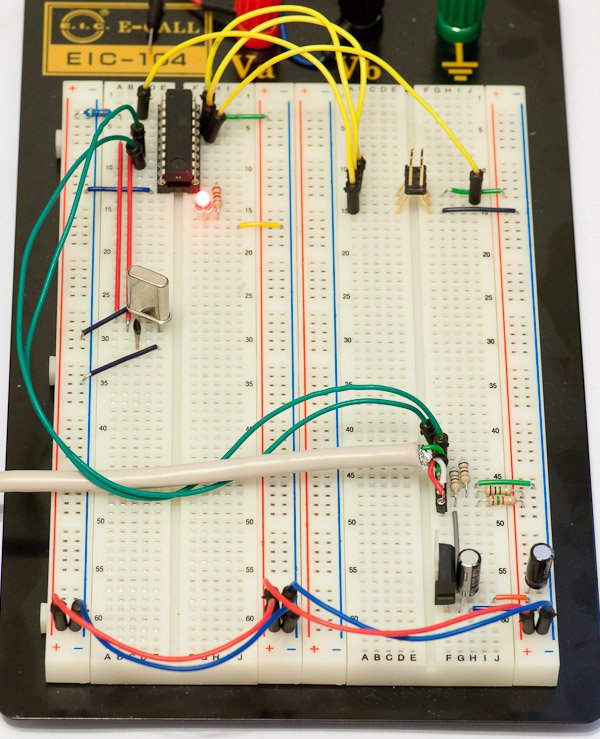
Update: Some people have noted that the setup I’m using here runs ATtiny2313 at 12 MHz with only 3.3V VCC, which is outside the specified range (frequencies over 10 Mhz require 4.5V or more). I’ve never had any problems, and many others have succeeded with this setup, but if you encounter persistent problems, I suggest you to power the ATtiny2313 straight from 5V of the USB line and use zener diodes on D+ and D- lines to drop their voltage, as is done in my later tutorial with the ATtiny85 microcontroller.
Breadboard setup
This time I will not walk you through every connection. Instead, I’ll just outline the steps needed and show the pictures of end result. Here is the schematic we’re building:
Basically it’s the regulator circuit we just built, pullups and line resistors for D+ and D- in the USB bus going to PD2 and PD3, and the ATtiny2313 with RESET pullup and MISO, MOSI, SCK and RESET connected to the 6-pin programming header, and a 12 MHz crystal. An easy order to make these connections is to:
- Reconstruct the power circuit from part 1 in one corner of the breadboard. Instead of connecting 5V from USB to the positive power rail, connect it straight to the input pin of the regulator – we won’t be needing 5V anywhere else
- Use jumper wires to connect regulator output and shared ground from USB to breadboard power rail
- If you have multiple power rails, you can use jumper wires to provide current to all of them
- Double-check the regulator pin connections and that capacitors are connected the right way
- Plug in the USB and use a multimeter to check you have 3.3V in power rails
- Insert the ATtiny and do standard wiring for power, reset pullup and 6-pin programming header
- If your programmer has a mode where it provides power to the chip – disable it
- Use programmer to check that the chip responds OK (i.e. gets power and acts in a stable manner)
- Connect the LED to PB0 and do a “test run” – flash a program that blinks the LED to see that it works
- Connect pullup resistors to D+ and D- (1M and 1k5)
- Connect D+ and D- to PD2 and PD3, respectively – use 68 ohm resistors in series here!
- Connect the 12 MHz crystal to PA1 and PA0, and ceramic capacitors between crystal pins and ground
For more detail: AVR ATtiny USB Tutorial Part 2
-
How do I connect the regulator input pin?
Connect 5V from USB straight to the input pin of the regulator instead of the positive power rail. -
What is the recommended order for making connections?
Reconstruct the power circuit first, then insert the ATtiny, connect the LED, attach pullup resistors, and finally connect the crystal. -
Which pins should the D+ and D- lines connect to?
Connect D+ and D- to PD2 and PD3 respectively using 68 ohm resistors in series. -
What happens if the ATtiny runs at 12 MHz with only 3.3V?
This setup operates outside the specified range where frequencies over 10 MHz require 4.5V or more, though it often works without issues. -
What should I do if I encounter persistent problems with the 12 MHz setup?
Power the ATtiny2313 directly from 5V of the USB line and use zener diodes on the D+ and D- lines to drop their voltage. -
Where does the 12 MHz crystal connect?
Connect the 12 MHz crystal to PA1 and PA0, placing ceramic capacitors between the crystal pins and ground. -
How can I verify the chip responds correctly before connecting USB data lines?
Use the programmer to check that the chip gets power and acts in a stable manner after flashing a test program. -
What value pullup resistors are needed for the reset pin?
A 4.7 kΩ pullup resistor is required for the reset pin connected to the 6-pin header.
