Summary of Interfacing rotary encoder to Atmega32
This article explains interfacing a 12-step mechanical rotary encoder (with optional push button) to an Atmega32. It describes wiring (A to PB2, B to PB3, button to PB4), using internal pull-ups, and polling the encoder from a Timer2 overflow ISR (~122 Hz with 16 MHz CPU, prescaler 256). A small rotary library (rotary.h/rotary.c) is provided with initialization, status checking, getting, and resetting functions. Rotary turns set rotarystatus: 1 = left, 2 = right, 3 = button. A KS0108 graphical LCD is mentioned for display.
Parts used in the Rotary Encoder Project:
- 12-step mechanical rotary encoder (SparkFun)
- Atmega32 microcontroller
- Wires for connections (3 wires: A, B, GND) plus button line
- Power supply for Atmega32
- Timer2 hardware on Atmega32 (internal peripheral)
- KS0108 based graphical LCD (for display)
- Toolchain for AVR C (compiler, headers, e.g., avr/io.h)
- rotary.c source file (library)
- rotary.h header file (library)
Recently I was working on a project that involved rotary encoder. I thought I’d share some thoughts on how rotary encoder can be interfaced and programmed. Actually it is easy to work with rotary encoders – interfacing is simple – only three wires are required to connect to microcontroller (two for signal (quadrature outputs) and one for reference (GND)). When turned there is a Grey code produced on outputs that allows tracking turn speed and direction. These features allow having convenient user interface with single knob. Many rotary encoders also comes with button – so menu navigation couldn’t be easier. In our project we are going to use a 12-step mechanical rotary encoder from sparkfun.
You can find many projects in internet where one of rotary encoder pins is connecter to microcontroller interrupt pin. This enables easier detection of encoder turn. Using endless loop isn’t recommended because it occupies lots of MCU resources and is inefficient. Another logical solution is to use Timer that periodically generates interrupts so it could check if rotary encoder have been turned or button have been pressed. Lets stick with timer option as it allows connecting encoder to any available microcontroller pins. Encoder is connected to Atmega32 as follows: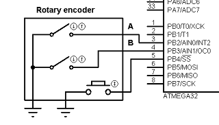
Encoder A pin to atmega32 pin B2; encoder pin B to MCU pin B3 and button to pin B4. We are going to use atemga32 internal pull-ups on these pins, so other encoder pins have to be connected to ground.
Lets write simple library for reading rotary encoder. This will make code more reusable and modular. To do so we create two empty files rotary.c and rotary.h. In rotary.h we define our port pins and library function prototypes:
#ifndef ROTARY_H
#define ROTARY_H
#include <avr/io.h>
//define port where encoder is connected
#define ROTPORT PORTB
#define ROTDDR DDRB
#define ROTPIN PINB
//define rotary encoder pins
#define ROTPA PB2
#define ROTPB PB3
#define ROTPBUTTON PB4
//define macros to check status
#define ROTA !((1<<ROTPA)&ROTPIN)
#define ROTB !((1<<ROTPB)&ROTPIN)
#define ROTCLICK !((1<<ROTPBUTTON)&ROTPIN)
//prototypes
void RotaryInit(void);
void RotaryCheckStatus(void);
uint8_t RotaryGetStatus(void);
void RotaryResetStatus(void);
#endif
In library source file we declare following functions. First of all initialize pins where rotary encoder is connected:
void RotaryInit(void)
{
//set pins as input
ROTDDR &= ~((1<<ROTPA)|(1<<ROTPB)|(1<<ROTPBUTTON));
//enable interrnal pullups;
ROTPORT |= (1<<ROTPA)|(1<<ROTPB)|(1<<ROTPBUTTON);
}
we set selected port pins as inputs and enable internal pull-up resistors.
Then follows our rotary check status function which sets our internal variable to some variable.
void RotaryCheckStatus(void)
{
//reading rotary and button
//check if rotation is left
if(ROTA & (!ROTB)){
loop_until_bit_is_set(ROTPIN, ROTPA);
if (ROTB)
rotarystatus=1;
//check if rotation is right
}else if(ROTB & (!ROTA)){
loop_until_bit_is_set(ROTPIN, ROTPB);
if (ROTA)
rotarystatus=2;
}else if (ROTA & ROTB){
loop_until_bit_is_set(ROTPIN, ROTPA);
if (ROTB)
rotarystatus=1;
else rotarystatus=2;
}
//check button status
if (ROTCLICK)
{
rotarystatus=3;
}
}
if know was turned left – rotary status is set to 1, if right then value is 2 and if button was pressed – status is set to 3.
Following two functions simply returns status and resets it:
//return button status
uint8_t RotaryGetStatus(void)
{
return rotarystatus;
}
//reset status
void RotaryResetStatus(void)
{
rotarystatus=0;
}
We are using a graphical LCD based on ks0108 controller for displaying messages. How co control it and how to set up library follow this post. We won’t go in to details on this.
To check rotary encoder status we are using Timer2 overflow interrupts. Microcontroller is running at 16MHz so with prescaller 256 overflow interrupt occur 122 times/s. Speed seems to be suitable for fluent operation.
void Timer2_Start(void)
{
TCCR2|=(1<<CS22)|(1<<CS21); //prescaller 256 ~122 interrupts/s
TIMSK|=(1<<TOIE2);//Enable Timer0 Overflow interrupts
}
After timer has been started we can put RotarryCheckStatus function inside it and read encoder actions:
ISR(TIMER2_OVF_vect)
{
//reading rotary and button
RotaryCheckStatus();
}
For more detail: Interfacing rotary encoder to Atmega32
- How many wires are required to connect the rotary encoder to the microcontroller?
Three wires: two quadrature signal lines and one reference (GND); additionally many encoders provide a button line. - How is the rotary encoder connected to the Atmega32 in this project?
Encoder A to PB2, encoder B to PB3, and encoder button to PB4 on the Atmega32. - Does the project use external resistors for encoder inputs?
No, the project uses Atmega32 internal pull-up resistors on the encoder pins. - What library files are created for handling the rotary encoder?
Two files: rotary.h (defines pins and prototypes) and rotary.c (implements initialization and status checking). - How does the code detect rotation direction and button press?
RotaryCheckStatus sets rotarystatus to 1 for left, 2 for right, and 3 for button press based on pin readings. - What method is used to poll the rotary encoder efficiently?
Timer2 overflow interrupts are used to call RotaryCheckStatus periodically instead of continuous polling. - What Timer2 settings are used for interrupt frequency?
With a 16 MHz MCU clock and prescaler 256 (TCCR2 bits CS22 and CS21), Timer2 overflows at about 122 interrupts per second. - Where is rotary polling placed in the firmware?
RotaryCheckStatus is called inside the ISR for TIMER2_OVF_vect. - How are the encoder input macros defined in rotary.h?
Macros ROTA, ROTB, and ROTCLICK evaluate the corresponding PINB bits inverted (using !((1<<pin)&ROTPIN)). - Is there display hardware mentioned for showing messages?
Yes, a KS0108 based graphical LCD is mentioned for displaying messages, with a separate library referenced.