
Summary of How to use I2C-bus on the Atmel AVR Microcontroller
### Summary This article explains the I2C bus, a simple two-wire communication protocol (SDA and SCL) introduced by Philips for connecting microcontrollers to various ICs like EEPROMs, sensors, and clocks. It details the master-slave architecture, 7-bit addressing allowing up to 128 devices, and demonstrates a practical project using an AVRJazz Mega168 board with a Microchip 24AA128 EEPROM to store and retrieve LED data patterns.
Parts used in the AVRJazz Mega168 I2C Project:
- AVRJazz Mega168 board
- Microchip 24AA128 I2C CMOS serial EEPROM
- ATMega168 microcontroller
- LEDs connected to PORT D
I2C (read as I Squared C) bus first introduced by Philips in 1980, because of its simplicity and flexibility the I2C bus has become one of the most important microcontroller bus system used for interfacing various IC-devices with the microcontroller. The I2C bus use only 2 bidirectional data lines for communicating with the microcontroller and the I2C protocol specification can support up to 128 devices attached to the same bus. Today many I2C IC-devices available on the market such as Serial EEPROM, I/O Expander, Real-Time Clock, Digital to Analog Converter, Analog to Digital Converter, Temperature Sensor and many more.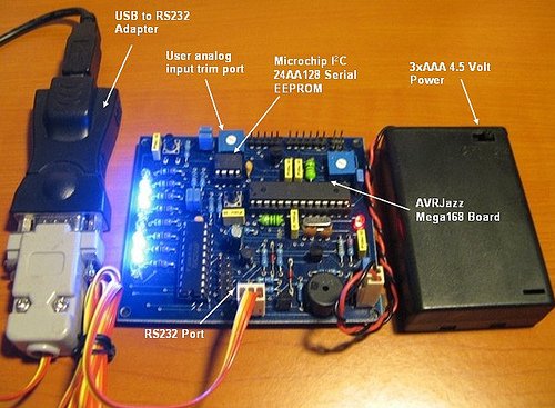
The I2C protocol use master and slave method, the master which is usually the microcontroller while the slave can be any I2C devices such as Serial EEPROM, I/O Expander or even another microcontroller. All of these devices connected to the I2C bus; one for the serial data called SDA (serial data) and the other for synchronize clock called SCL (serial clock); each of these slave devices has their own individual 7 bits of the address length.
The 7 bits address consists of 4 bits device identification and 3 bits device physical address. For example if we want to use the Microchip 24AA128 I2C CMOS serial EEPROM, the first 4 bits for this device identification is “1010” and the last 3 bits could be selected by setting the appropriate address at pins A0, A1 and A2 on the serial EEPROM. Therefore by using these 3 bits we could attach up to 8 Microchip 24AA128 serial EEPROM on the same I2C bus; which give you total of 8 x 16 Kbytes of memory.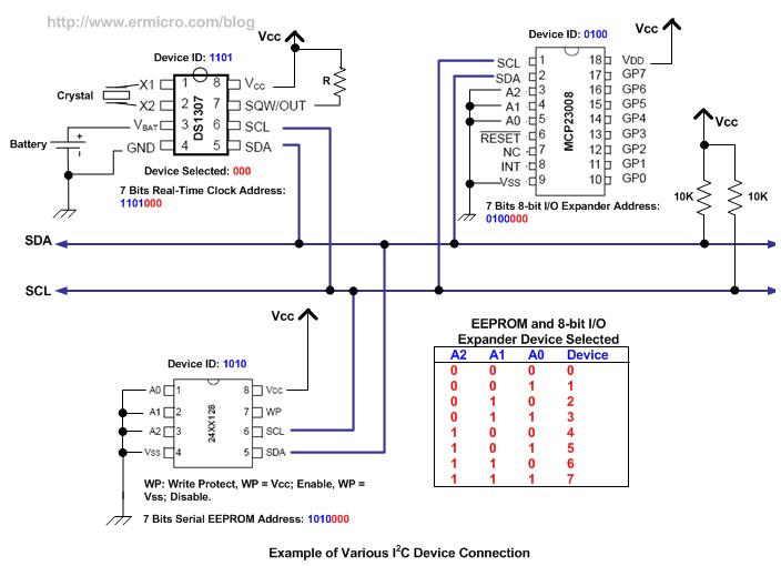
The same principal also applies to the other I2C-bus devices such as the Microchip MCP23008 8-bit I/O Expander and Dalas DS1307 Real Time Clock (see the example picture). By selecting the appropriate device address, the master can easily communicate with the entire slave devices connected to the I2C bus; the I2C bus protocol only allowed one connection to be established between master and slave at a time. With this powerful and yet simple concept you could see the enormous possibility of using these I2C bus devices for the embedded application.
In this tutorial we will use the AVRJazz Mega168 board from ermicro that has build in Microchip 24AA128 I2C serial EEPROM on the board; we will use this EEPROM for storing the LEDs data pattern and later on we will read the data and display it to the LEDs attached to the AVR ATMega168 microcontroller on the PORT D.
The principal we learn on this I2C serial EEPROM device can be applied to other I2C devices as well, the differences is only on the terms used; on the serial EEPROM we use memory address for storing and retrieving the data, while on the other I2C devices such as Microchip MCP23008 8-bit I/O expander or Dalas DS1307 Real Time Clock we use register address for writing and reading the data.
For more detail: How to use I2C-bus on the Atmel AVR Microcontroller
- What is the I2C bus?
The I2C bus is a microcontroller bus system introduced by Philips in 1980 that uses only two bidirectional data lines for simplicity and flexibility. - How many devices can the I2C protocol support?
The I2C protocol specification can support up to 128 devices attached to the same bus. - Which two lines are used for I2C communication?
All devices connect to one line for serial data called SDA and another for the synchronize clock called SCL. - How is the 7-bit address structured?
The 7-bit address consists of 4 bits for device identification and 3 bits for the device physical address. - Can multiple identical EEPROMs be used on one bus?
Yes, by setting appropriate addresses at pins A0, A1, and A2, up to 8 identical devices can be attached to the same I2C bus. - Does the I2C protocol allow simultaneous connections?
No, the I2C bus protocol only allows one connection to be established between the master and a slave at a time. - What hardware is used in this specific tutorial?
The tutorial uses an AVRJazz Mega168 board from ermicro that has a built-in Microchip 24AA128 I2C serial EEPROM. - How do you distinguish between EEPROM and other I2C devices?
On serial EEPROMs, memory addresses are used for storing and retrieving data, whereas other devices use register addresses.
