Summary of DS1307 RTC Interfacing with AVR microcontroller
In this tutorial the DS1307 I2C real-time clock is interfaced with an Atmega8 AVR microcontroller to display and set time/date on an LCD. It explains DS1307 features, pin functions, I2C timing, read/write cycles, typical circuit connections, and provides AVR C code for initializing an LCD, communicating with the DS1307 over I2C, setting time/date, and displaying current time and date.
Parts used in the DS1307 RTC Interfacing Project:
- DS1307 Real-Time Clock (8-pin)
- Atmega8 microcontroller
- 16x2 LCD display (HD44780-compatible)
- 32.768 kHz quartz crystal (for DS1307 X1/X2)
- 3V lithium backup battery (VBAT) or backup supply
- Pull-up resistors for SDA and SCL (I2C bus)
- Optional pull-up resistor for SQW/OUT pin
- Decoupling capacitors and power supply components
- Connecting wires and PCB or breadboard
In this tutorial we will learn How to interface RTC DS1307 with AVR microcontroller.
We are using Atmega8 for the demo.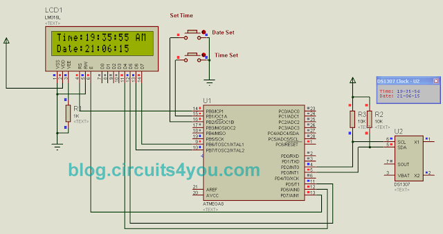
GENERAL DESCRIPTION
The DS1307 serial real-time clock (RTC) is a low-power, full binary-coded decimal (BCD)
clock/calendar plus 56 bytes of NV SRAM. Address and data are transferred serially through
an I2C™, bidirectional bus. The clock/calendar provides seconds, minutes, hours, day, date,
month, and year information. The end of the month date is automatically adjusted for months
with fewer than 31 days, including corrections for leap year. The clock operates in either the 24-
hour or 12-hour format with AM/PM indicator. The DS1307 has a built-in power-sense circuit
that detects power failures and automatically switches to the battery supply.
FEATURES
- Real-Time Clock (RTC) Counts Seconds, Minutes, Hours, Date of the Month, Month,
- Day of the week, and Year with Leap-Year Compensation Valid Up to 2100
- 56-Byte, Battery-Backed, Nonvolatile (NV) RAM for Data Storage
- I2C Serial Interface
- Programmable Square-Wave Output Signal
- Automatic Power-Fail Detect and Switch Circuitry
- Consumes Less than 500nA in Battery-Backup Mode with Oscillator Running
- Optional Industrial Temperature Range: -40°C to +85°C
- Available in 8-Pin DIP or SO
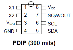 PIN DESCRIPTION:
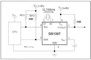
X1 and X2 (pin 1,2): Connections for Standard 32.768kHz Quartz Crystal. The internal oscillator circuitry is designed for operation with a crystal having a specified load capacitance (CL) of 12.5pF. X1 is the input to the oscillator and can optionally be connected to an external 32.768kHz oscillator. The output of the internal oscillator, X2, is floated if an external oscillator is connected to X1.
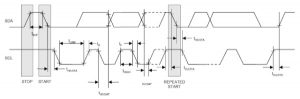
and making SDA Line from High to Low.
2. Similarly I2C Stop Condition is generated by making SDA Line Low to High transition.
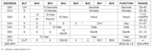
Time Keeper Register:
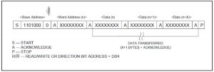
Data Write Cycle:
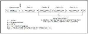
Data Read Cycle:
//===========================================
/* DS1307 Real Time Clock Software          */
/* 2nd Dec 2014                             */
/* Copyright 2015 Circuits4You.com          */
/* WWW - http://blog.circuits4you.com       */
/* Email - [email protected]            */

/*LCD Pin-5(R/W) must be connected to ground*/
//===========================================

//Note: 1. Define Clock in Configuration Opetions
//      2. Define RTC Connections in i2c.h
#include <avr/io.h>
#include <string.h>
#include "delay.h"
#include "i2c.h"

#define E   PD7
#define RS   PB0

void display(char string[16]);
void displaybyte(char D);
void dispinit(void);
void epulse(void);
void delay_ms(unsigned int de);
void line1();
void line2();


void SetTime(char HH,char MM, char SS, char ampm);
char GetHH();
char GetMM();
char GetSS();

void SetDate(char DD,char MM, char YY);
char GetDD();
char GetMonth();
char GetYY();

void DisplayDateTime();

int Read_RTC(char add);
int Write_RTC(char add,char data1);


char mystr[8];
int temp;
//====================================
//        Main Function
//====================================
int main(void)
{
 int set;

 DDRB = 0xE1;  //Set LCD Port Direction
 DDRD = 0xE0;
 PORTB = 0x06; //Pull up for switches

  delay_ms(500);  //Initiaize LCD
  dispinit();
  delay_ms(200);
  while(1)
  {
  //Change Date/Time
  if((PINB & 0x02)==0x00) //Time Set Switch is pressed
  {
   SetTime(11,11,11, 1);
  }

  if((PINB & 0x04)==0x00) //Date Switch is pressed
  {
   SetDate(21,12,12);
  }
  DisplayDateTime();

  }
}

//=========================================
//  LCD Display Initialization Function
//=========================================
void dispinit(void)
{
 int count;
 char init[]={0x43,0x03,0x03,0x02,0x28,0x01,0x0C,0x06,0x02,0x02};

 PORTB &= ~(1<<RS);           // RS=0
 for (count = 0; count <= 9; count++)
  {
 displaybyte(init[count]);
  }
 PORTB |= 1<<RS;    //RS=1
}


//===================================
//     Enable Pulse Function
//===================================
void epulse(void)
{
 PORTD |= 1<<E;
  delay_ms(10); //Adjust delay if required
 PORTD &= ~(1<<E);
 delay_ms(10); //Adjust delay if required
}


//================================================
//  Send Single Byte to LCD Display Function
//================================================
void displaybyte(char D)
{
//D4=PD6
//D5=PD5
//D6=PB7
//D7=PB6
 //data is in Temp Register
  char K1;
  K1=D;
  K1=K1 & 0xF0;
  K1=K1 >> 4;  //Send MSB

  PORTD &= 0x9F;  //Clear data pins
  PORTB &= 0x3F;

  if((K1 & 0x01)==0x01){PORTD |= (1<<PD6);}
  if((K1 & 0x02)==0x02){PORTD |= (1<<PD5);}
  if((K1 & 0x04)==0x04){PORTB |= (1<<PB7);}
  if((K1 & 0x08)==0x08){PORTB |= (1<<PB6);}

 epulse();

  K1=D;
  K1=K1 & 0x0F;  //Send LSB
  PORTD &= 0x9F;  //Clear data pins
  PORTB &= 0x3F;

  if((K1 & 0x01)==0x01){PORTD |= (1<<PD6);}
  if((K1 & 0x02)==0x02){PORTD |= (1<<PD5);}
  if((K1 & 0x04)==0x04){PORTB |= (1<<PB7);}
  if((K1 & 0x08)==0x08){PORTB |= (1<<PB6);}
 epulse();
}

//=====================================================
//  Display Line on LCD at desired location Function
//=====================================================
void display(char string[16])
{
 int len,count;

 PORTB |= (1<<RS);           // RS=1 Data Mode
  len = strlen(string);

   for (count=0;count<len;count++)
  {
    displaybyte(string[count]);
 }
}

void line1()
{
        PORTB &= ~(1<<RS);           // RS=0 Command Mode
  displaybyte(0x80);  //Move Coursor to Line 1
  PORTB |= (1<<RS);           // RS=1 Data Mode
}
void line2()
{
        PORTB &= ~(1<<RS);           // RS=0 Command Mode
  displaybyte(0xC0);  //Move Coursor to Line 2
  PORTB |= (1<<RS);           // RS=1 Data Mode
}
//============================================
//        Delay Function
//============================================
void delay_ms(unsigned int de)
{
unsigned int rr,rr1;
   for (rr=0;rr<de;rr++)
   {

  for(rr1=0;rr1<30;rr1++)   //395
  {
   asm("nop");
  }

   }
}
//==============================================
//            RTC1307_READ_WRITE             //
//==============================================
int Read_RTC(char add)
{
 int temp1;
 I2C_START_TX(0b11010000);
 i2c_transmit(add);
 i2c_start();
 I2C_START_RX(0b11010000);
 temp1 = i2c_receive(0);
 i2c_stop();
 return(temp1);
}

int Write_RTC(char add,char data1)
{
 I2C_START_TX(0b11010000); //device add.
    i2c_transmit(add); //Reg. add.
 i2c_transmit(data1);
 i2c_stop();
return 0;
}

//=================================
//          SET TIME
//=================================
void SetTime(char HH,char MM, char SS, char ampm)
{
 sprintf(mystr,"%03d",SS);
 Write_RTC(0x00,((mystr[1] - 0x30) << 4) | (mystr[2] - 0x30));

 sprintf(mystr,"%03d",MM);
 Write_RTC(0x01,((mystr[1] - 0x30) << 4) | (mystr[2] - 0x30));


 sprintf(mystr,"%03d",HH);
 if(ampm == 1)
 {
  Write_RTC(0x02,((((mystr[1] - 0x30) << 4) | (mystr[2] - 0x30)) | 0x40) | 0x20);
    }
 else
 {
  Write_RTC(0x02,((((mystr[1] - 0x30) << 4) | (mystr[2] - 0x30)) | 0x40));
 }
}
//==========================================
char GetHH()
{
 return Read_RTC(0x02);
}
//===========================================
char GetMM()
{
 return (Read_RTC(0x01) & 0x7F);
}
//===========================================
char GetSS()
{
 return Read_RTC(0x00);
}
//============================================
//                   SET DATE
//============================================
void SetDate(char DD,char MM, char YY)
{
 sprintf(mystr,"%03d",DD);
 Write_RTC(0x04,((mystr[1] - 0x30) << 4)  | (mystr[2] - 0x30));

 sprintf(mystr,"%03d",MM);
 Write_RTC(0x05,((mystr[1] - 0x30) << 4) | (mystr[2] - 0x30));

 sprintf(mystr,"%03d",YY);
 Write_RTC(0x06,((mystr[1] - 0x30) << 4)  | (mystr[2] - 0x30));
}
//===========================================
char GetDD()
{
 return Read_RTC(0x04);
}
//===========================================
char GetMonth()
{
 char j;
 j=Read_RTC(0x05);
 j=(j & 0x0F) + ((j >> 4) * 10);
 return j; //12/11
}
//===========================================
char GetYY()
{
 char k;
 k=Read_RTC(0x06);
 k=(k & 0x0F) + ((k >> 4) * 10);
 return k;
}
//============================================
//              Display Date and Time
//============================================
void DisplayDateTime()
{
  temp = Read_RTC(0x00);

  mystr[7]=48+(temp & 0b00001111);
  mystr[6]=48+((temp & 0b01110000)>>4);
  mystr[5]=':';

  temp = Read_RTC(0x01);

  mystr[4]=48+(temp & 0b00001111);
  mystr[3]=48+((temp & 0b01110000)>>4);
  mystr[2]=':';

  temp = Read_RTC(0x02);

  mystr[1]=48+(temp & 0b00001111);
  mystr[0]=48+((temp & 0b00010000)>>4);

  line1();
  display("Time:");

  displaybyte(mystr[0]);
  displaybyte(mystr[1]);
  displaybyte(mystr[2]);
  displaybyte(mystr[3]);
  displaybyte(mystr[4]);
  displaybyte(mystr[5]);
  displaybyte(mystr[6]);
  displaybyte(mystr[7]);

  temp = Read_RTC(0x02);
  temp = temp & 0x20;
  if(temp == 0x20)
  {
   display(" PM");
  }
  else
  {
   display(" AM");
  }
  temp = Read_RTC(0x06);

  mystr[7]=48+(temp & 0b00001111);
  mystr[6]=48+((temp & 0b01110000)>>4);
  mystr[5]=':';

  temp = Read_RTC(0x05);

  mystr[4]=48+(temp & 0b00001111);
  mystr[3]=48+((temp & 0b01110000)>>4);
  mystr[2]=':';

  temp = Read_RTC(0x04);

  mystr[1]=48+(temp & 0b00001111);
  mystr[0]=48+((temp & 0b00110000)>>4);

  line2();
  display("Date:");

  displaybyte(mystr[0]);
  displaybyte(mystr[1]);
  displaybyte(mystr[2]);
  displaybyte(mystr[3]);
  displaybyte(mystr[4]);
  displaybyte(mystr[5]);
  displaybyte(mystr[6]);
  displaybyte(mystr[7]);
}
- What microcontroller is used in the demo?
The Atmega8 AVR microcontroller is used for the demo. - How does the DS1307 communicate with the microcontroller?
The DS1307 communicates via the I2C serial interface using SDA and SCL lines. - What crystal frequency is required for the DS1307?
A standard 32.768 kHz quartz crystal is used on X1 and X2. - Can the DS1307 keep time when VCC is removed?
Yes, the DS1307 has a VBAT backup input that allows timekeeping to continue when VCC is removed. - How is I2C start and stop condition generated?
I2C Start is generated by keeping SCL high and changing SDA from high to low; Stop is SDA low to high while SCL is high. - What is the 7-bit I2C address of the DS1307?
The DS1307 7-bit address is 1101000. - What additional memory does the DS1307 provide?
The DS1307 includes 56 bytes of battery-backed nonvolatile RAM. - What square-wave frequencies can SQW/OUT output?
When enabled, SQW/OUT can output 1 Hz, 4 kHz, 8 kHz, or 32 kHz. - How are time and date written to the DS1307?
The master writes the register address after the slave address and then transmits data bytes; the register pointer auto-increments after each write. - How does the DS1307 handle month-end and leap years?
The clock/calendar automatically adjusts the end-of-month date for months with fewer than 31 days and includes leap-year corrections.