
Summary of AVR Serial Communication (UART) Programming tutorial
This tutorial explains AVR UART serial communication: registers (UDR, UBRR, UCSRA, UCSRB, UCSRC), configuring baud rate (example: UBRR=0x33 for 8MHz/9600), transmission and reception steps, and example AVR C code that sends "BGN" to a PC via MAX232 and displays received characters on a 16×2 LCD. It outlines flag checks, clearing flags, and LCD routines for displaying characters and moving the cursor.
Parts used in the AVR Serial Communication (UART) Project:
- AVR microcontroller
- MAX232 level converter IC
- 16×2 LCD
- PC with hyperterminal (or terminal emulator)
- Connection cables (TX/RX, power, ground)
- Crystal oscillator or MCU clock (8 MHz in example)
- Power supply
- Resistors and miscellaneous prototyping components
This tutorial focuses to teach you how to program AVR Serial Communication (UART). UART plays an important role in almost every embedded applications which we see in our day to life and hence it was considered to be very important concept in every Microcontroller.
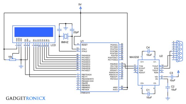
The above design demonstrates the usage of UART to send and receive data via hyperterminal as well display the received data in 1 16×2 LCD. As we all know Microcontroller works in TTL logic which is not compatible with the PC so we have to employ a level converter IC MAX232, read more about the working of IC MAX232.
REGISTERS USED IN AVR SERIAL COMMUNICATION:
In AVR there are five registers which are meant to use for Serial Communication such as UDR, UBBR , UCSRA, UCSRB, UCSRC. Lets see the functions of these registers briefly.
UDR:
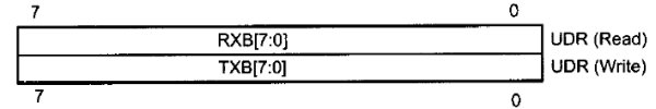
UDR or USART Data Register is meant for writing and receiving the data through the UART. In this there are two shift registers referred to as Transmit Shift register and Receive Shift register with each having a separate buffer register. When the data is written to UDR it will be transferred to Transmit Data buffer register and when we read the contents of the Receive Data buffer register is returned.
UBRR:
In AVR the baud rate of the UART is programmable and it is achieved by means of this UBRR register. It is 16 bit register classified into lower UBRRL and higher UBRRH out of which 12 bit is usable The formula governing the relation between the value of UBRR and Oscillator is
Baud Rate = (Oscillator Frequency / (16( UBRR Value +1))
So for a 8MHz oscillator frequency and 9600 baud rate the value need to be loaded in the UBRR will be
UBRR = (8MHZ /16(9600))-1
=(500KHz/ 9600) – 1
= 51 ( equivalent hex 33)
UCSRA:

UCSRB:
UCSRB:

UCSRC Register:

STEPS TO PROGRAM UART:
- Load the hex value in the UBRR Register for the Baud rate you are about to use.
- Set the bits in the registers UCSRA, UCSRB & UCSRC based on your usage requirement.
- For Transmission Place the data in the UDR register and check for the appropriate flag to set in the UCSRA regsiter
- Clear the Flag for further transmission.
- For receiving the data, wait for the Receive flag to set in the UCSRA register and then read the UDR register to obtain the received data for processing or display.
- Clear the Flag for further data reception.
CODE:
#include<avr/io.h>
#define F_CPU 8000000UL
#include<util/delay.h>
void display(char a,int b);     //LCD display routine
void check();
char c;
int i,cursor;
int main(void)
{
  DDRA=0xff;                      //Setting Directions
  DDRB=0x03;
  display(0x38,0);
  display(0x0f,0);
  display(0x80,0);
  UBRRL=0x33;                 //Hex value for Baud rate 9600
  UCSRB=0x18;                //Initialization of UCSRB reg
  UCSRC=0x06;                //Initialization of UCSRC reg
  while(!(UCSRA&(1<<5)));    //Flag Check
  UDR='B';                            //Data write in UDR
  UCSRA&=~(1<<5);             //Clearing Flag
  while(!(UCSRA&(1<<5)));
  UDR='G';
  UCSRA&=~(1<<5);
  while(!(UCSRA&(1<<5)));
  UDR='N';
  UCSRA&=~(1<<5);

   while(1)
   {
     while(!(UCSRA&(1<<7)));   //Flag check for receive
     c=UDR;                             //Data Read
     display(c,1);                      //Displaying received data in LCD
     UCSRA&=~(1<<7);
     check();
   }
 }

void display(char a,int b)       //LCD routine
 {
  PORTA=a;
  if(b==0)
   {
     PORTB&=~(1<<0);
   }
  else
   {
     PORTB|=(1<<0);
     cursor++;
    }
  PORTB|=(1<<1);
  _delay_ms(10);
  PORTB&=~(1<<1);
  _delay_ms(10);
 }

void check()                   //Routine to print data continuously
 {
   if(cursor==16)
   {
    display(0xc0,0);       //Jumps second row after reaching end of first row
   }
   else if(cursor==32)
   {
     display(0x80,0);    //Jumps first row after reaching end of second row
     cursor=1;
   }
 }
Related content
Read More: AVR Serial Communication (UART) Programming tutorial
- What registers are used for AVR Serial Communication?
The registers are UDR, UBRR, UCSRA, UCSRB, and UCSRC. - How is baud rate set in AVR UART?
By loading a value into the 16-bit UBRR register; example UBRR=0x33 for 8MHz and 9600 baud. - How do you transmit data via UART in the provided code?
Place data in UDR, wait for the transmit flag in UCSRA, and clear the flag after transmission. - How do you receive data via UART in the provided code?
Wait for the receive flag in UCSRA to set, read received data from UDR, then clear the flag. - Why is MAX232 used in this project?
Because the microcontroller uses TTL logic which is not directly compatible with PC serial levels, so MAX232 level conversion is required. - What initial data does the controller send to hyperterminal?
The controller sends the string BGN to the hyperterminal at startup. - How is received data displayed in this project?
Received characters read from UDR are sent to a 16×2 LCD using the display routine. - What clock and baud example values are used in the tutorial?
The tutorial uses an 8 MHz oscillator and 9600 baud as the example.