
Summary of LED Driver MAX7219 – clock
This article describes wiring a MAX7219 IC to an ATMEGA328 microcontroller and a common cathode 4-digit 7-segment display. It specifies using two capacitors for noise reduction and one resistor (minimum 10kΩ) to limit LED current. The system requires 5VDC power, shared ground connections, and three digital signal lines for data transmission.
Parts used in the MAX7219 Display Project:
- MAX7219 IC
- ATMEGA328 microcontroller board
- 4 digit 7-segment display (common cathode)
- Two capacitors
- One resistor (at least 10kohm)
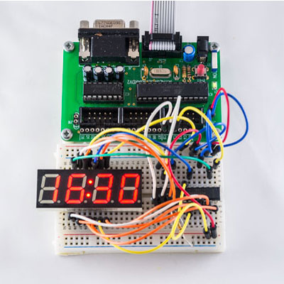
Below is the schematic that shows how the IC is wired to the ATMEGA328 microcontroller and the 4 digit 7-segment display with comon cathode.
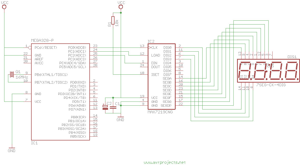
Besides the MAX7219 you need only three other external components: two capacitors and one resistor.
The capacitors are here to reduce noise signals and cannot be ommited.
The resistor is used to set the limit for the LED’s current. It should be at least 10kohm. The MAX7219 has to be powered with 5VDC. It is possible to use the +5V of the ATMEGA328 board. Both the ground pins of the MAX7219 have to be connected to the ATMEGA328 board.
The three signal lines (DIn,CLK,Load(/CS)) have to be connected to three digital outputs on the ATMEGA328 board.
for more detail: LED Driver MAX7219 – clock
- What external components are needed besides the MAX7219?
You need two capacitors and one resistor. - Why are the two capacitors required?
The capacitors reduce noise signals and cannot be omitted. - What is the function of the resistor in this project?
The resistor sets the limit for the LED's current. - What is the minimum resistance value recommended for the resistor?
The resistor should be at least 10kohm. - What voltage is required to power the MAX7219?
The MAX7219 has to be powered with 5VDC. - Can the +5V from the ATMEGA328 board be used?
Yes, it is possible to use the +5V of the ATMEGA328 board. - How many signal lines connect the IC to the microcontroller?
Three signal lines connect the IC to the microcontroller. - Which pins on the ATMEGA328 receive the signal lines?
The signal lines must be connected to three digital outputs on the ATMEGA328 board.
