
Summary of Temperature-to-period circuit provides linearization of thermistor response
This article describes a circuit that linearizes the nonlinear response of thermistors by converting temperature into a proportional time period. By paralleling a resistor with the thermistor and utilizing an RC oscillator driven by a JFET current regulator, the design achieves high linearity (under 0.1K error) over a 30K range, allowing for digital frequency counting.
Parts used in Thermistor Linearization Circuit:
- Thermistor (RT)
- Parallel Resistance (RP)
- JFET (Q1)
- Resistor (RS)
- Buffer-amplifier IC1
- Resistor (R4)
- Resistor (R1)
- Capacitor (C1)
- Resistor (R2)
- Comparator IC2
Designers often use thermistors rather than other temperature sensors because thermistors offer high sensitivity, compactness, low cost, and small time constants. But most thermistors’ resistance-versus-temperature characteristics are highly nonlinear and need correction for applications that require a linear response. Using a thermistor as a sensor, the simple circuit in Figure 1 provides a time period varying linearly with temperature with a nonlinearity error of less than 0.1K over a range as high as 30K. You can use a frequency counter to convert the period into a digital output. An approximation derived from Bosson’s Law for thermistor resistance, RT, as a function of temperature, θ, comprises RT=AB–θ (see sidebar “Exploring Bosson’s Law and its equation”). This relationship closely represents an actual thermistor’s behavior over a narrow temperature range.
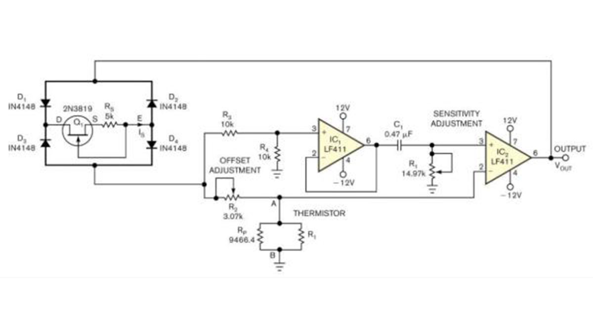
Figure 1
This simple circuit linearizes a thermistor’s response and produces an output period that’s proportional to temperature.
You can connect a parallel resistance, RP, of appropriate value across the thermistor and obtain an effective resistance that tracks fairly close to AB–θ  30K. In Figure 1, the network connected between terminals A and B provides an effective resistance of RAB AB–θ. JFET Q1 and resistance RS form a current regulator that supplies a constant current sink, IS, between terminals D and E.
Through buffer-amplifier IC1, the voltage across R4 excites the RC circuit comprising R1 and C1 in series, producing an exponentially decaying voltage across R1 when R2 is greater than RAB. At the instant when the decaying voltage across R1 falls below the voltage across thermistor RT, the output of comparator IC2changes its state. The circuit oscillates, producing the voltage waveforms in Figure 2 at IC2‘s output. The period of oscillation, T, is T=2R1C1ln(R2/RAB)2R1C1[ln(R2/A)+θlnB]. This equation indicates that T varies linearly with thermistor temperature θ.
Read more: Temperature-to-period circuit provides linearization of thermistor response
-
Why do designers often choose thermistors over other sensors?
Designers use thermistors because they offer high sensitivity, compactness, low cost, and small time constants. -
How does the circuit handle the nonlinear resistance of thermistors?
The circuit connects a parallel resistance across the thermistor to create an effective resistance that tracks closely to the required linear approximation. -
What is the maximum nonlinearity error achieved by this design?
The circuit provides a nonlinearity error of less than 0.1K over a range as high as 30K. -
How can the output period be converted into a digital value?
You can use a frequency counter to convert the oscillation period into a digital output. -
What equation approximates the thermistor resistance behavior?
Bosson's Law approximation states that RT equals AB minus theta, where theta represents the temperature. -
What component supplies the constant current sink in the circuit?
The JFET Q1 and resistance RS form a current regulator that supplies a constant current sink between terminals D and E. -
When does the comparator IC2 change its state?
The comparator changes state when the exponentially decaying voltage across R1 falls below the voltage across the thermistor RT. -
Does the oscillation period vary linearly with temperature?
Yes, the derived equation indicates that the period T varies linearly with the thermistor temperature theta.
