Summary of Basic Mobile Phone Using STM32F407 Discovery Kit and GSM A6 Module
This article guides users in building a basic mobile phone using the STM32F407 Discovery Kit and GSM A6 module. The microcontroller manages calls, SMS, display output via an LCD 16x02, and input through a hex keypad. The project involves organizing driver code for each component within the Keil uVision IDE to create a functional embedded system.
Parts used in the Basic Mobile Phone Project:
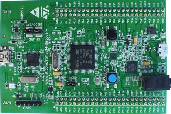
- STM32F407 Discovery Kit
- GSM A6 Module
- LCD 16x02 Display
- I2C Module
- Hex Keypad
- Jumper cables
- Bread Board
- Speaker (8Ω)
- Microphone
Have you ever wanted to create a cool embedded project?. If yes, how about building one of the most popular and everyone’s favorite gadget i.e Mobile Phone!!!. In this Instructable, I will guide you on how to build a basic mobile phone using the STM32F407 Discovery Kit and GSM A6 module.
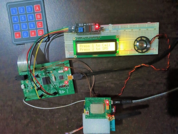
This project contains 3 main modules :
- GSM A6 Module – This is module is responsible for Making/Receiving Calls and SMS.
- LCD 16×02 Display – To see the output
- Hex Keypad – To give input
The STM32F407 MCU controls the GSM A6, LCD, and Keypad. So to make programming simple and organized, I developed individual driver code for Interfacing GSM A6 module, LCD and Keypad on STM32F407 MCU. Then I simply included these driver files in the main program and called respective APIs. You can find these driver codes in the Supplies below.
The Entire Keil Project file is included below
Supplies:
- Complete details on STM32F407 Discovery Kit Getting started with STM32F407 Discovery Kit
- Basic details about GSM A6 Module
- GitHub RepositoryBasic Mobile Phone Using STM32F407 Discovery kit and GSM module A6 Module
- Interfacing 16×02 LCD on STM32F407 Discovery using the I2C module.
- Interfacing 4X4 Matrix Keypad on STM32F407 Discovery Kit
- Interfacing GSM-A6 Module on STM32F407 Discovery Kit
Step 1: Components List
The hardware components required for this project are :
- STM32F407 Discovery Kit
- GSM A6 Module
- LCD 16×02
- I2C module
- Hex Keypad
- A couple of Jumper cables
- Bread Board
- Speaker (8Ω)
- Microphone
Step 2: Make the Connections
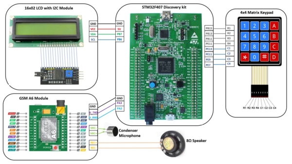
Connect the components as given in the above picture. This picture/diagram gives you a very realistic and easy way to connect all the components. 🙂
Note: GSM A6 Module is powered using a micro USB connector. You can use any mobile charger for powering up the GSM A6.
Step 3: Open Keil UVision IDE
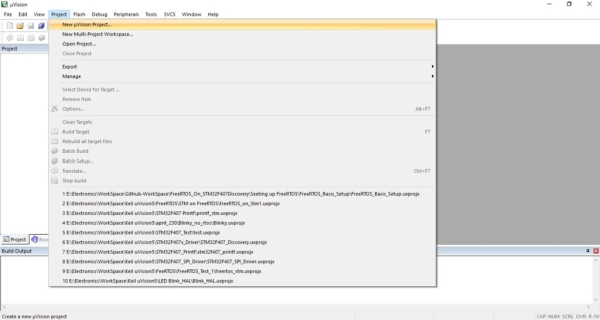
Open Keil uVision IDE. Click on a project the select New uVision Project…Then select your working directory and give your preferred project name.
Step 4: Select the Device
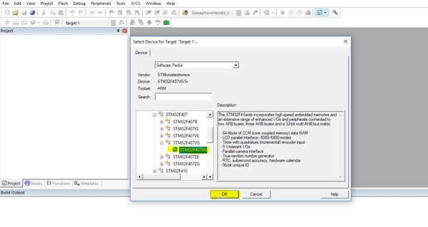
Once you have given a name to the project, in the next step you need to add a device. Here we are adding STM32F407VG Micronconroller from STMicroelectronics. Select the STM32F407VG, then Click OK.
Step 5: Manage Run-Time Environment
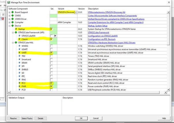
The next step is to select the library/driver component in the Manage Run-Time Environment Tab. Here select all components as shown in the above picture. Once you check all appropriate field Click Resolve then Click OK.
Step 6: Copy the Driver Files Int to Project Folder
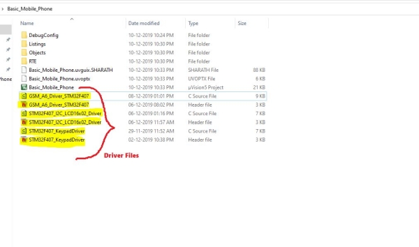
Now you have to add driver files for GSM A6 Module, LCD and Keypad. The driver files are :
1. GSM A6 Module :
GSM_A6_Driver_STM32F407.cand GSM_A6_Driver_STM32F407.h
2. LCD :
STM32F407_I2C_LCD16x02_Driver.c and STM32F407_I2C_LCD16x02_Driver.h
3. Keypad
STM32F407_KeypadDriver.c and STM32F407_KeypadDriver.h
Copy all these 6 files into your project folder. I have attached these files below
Step 7: Add the Driver Files to Your Project
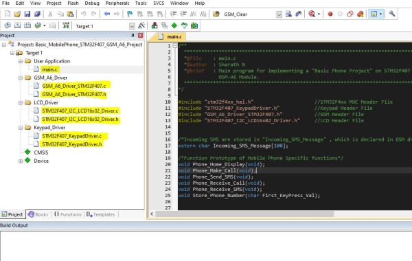
Once you have copied the Driver files into inside your project folder, you have to add these files to your Project.
In Keil, Select Target1, right-click then select Add new group. Create 4 new groups and Rename them as :
1) User Application – Here add new “main.c“ file.
2) GSM_A6_Driver – Add existing “GSM_A6_Driver_STM32F407.c” and “GSM_A6_Driver_STM32F407.h“ files to this gorup.
3) LCD_Driver – Add existing “STM32F407_I2C_LCD16x02_Driver.c” and “STM32F407_I2C_LCD16x02_Driver.h“ files to this group
4) Keypad_Driver – Add existing “STM32F407_KeypadDriver.c“ and “STM32F407_KeypadDriver.h“ files to this group
Note: I have included “main.c” file below, you can either directly add this file or copy its contents to the newly created main file.
Source: Basic Mobile Phone Using STM32F407 Discovery Kit and GSM A6 Module
- What is the main purpose of the GSM A6 module?
This module is responsible for making and receiving calls as well as sending and receiving SMS messages. - Which microcontroller controls the entire project?
The STM32F407 MCU controls the GSM A6 module, the LCD display, and the keypad. - How should the GSM A6 module be powered?
The GSM A6 module is powered using a micro USB connector connected to any mobile charger. - Which IDE is recommended for this project?
The article recommends opening the Keil uVision IDE to manage the project files. - What specific device must be selected in the IDE?
You must select the STM32F407VG Microcontroller from STMicroelectronics when adding a device. - How many groups should be created in Target1?
You need to create four new groups named User Application, GSM_A6_Driver, LCD_Driver, and Keypad_Driver. - Can I find the driver codes online?
Yes, the driver codes are available in the Supplies section including links to GitHub and specific interfacing guides. - What library components need to be resolved?
All appropriate fields in the Manage Run-Time Environment tab must be checked and resolved before proceeding.