
Summary of Arduino EMF (Electromagnetic Field) Detector
This article details a DIY project modifying an existing EMF detector to display readings on a 7-Segment LED instead of an LED bargraph. The author credits Aaron ALAI and Conner Cunningham for the original concepts. The guide covers necessary components, tools, and specific wiring instructions connecting the Arduino pins (2-8) to the display segments using resistors and a breadboard.
Parts used in the Arduino EMF Detector with 7-Segment Display:
- Arduino
- 7-Segment LED Display
- 3.3M Resistor
- 470 ohm resistor
- 26 gauge wire
- Breadboard
- Computer with Arduino IDE
- USB A-B cable for Arduino
- Wire Strippers
A while back I saw an EMF (Electromagnetic Field) Detector at makezine.com that used a led bargraph. I decided to modify it to use a 7-Segment LED Display! Here’s my project. Sorry I don’t have any pictures of it in use. Hopefully I can post some soon.
Credit goes to Aaron ALAI for the original project. Also Conner Cunningham at Make: for doing a remake.
Have fun, work hard, & play nice! If you have questions please ask them
Step 1: The Stuff:

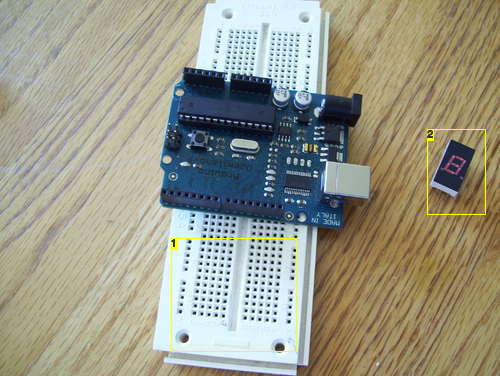
The parts & tools.
Parts:
– Arduino
– 7-Segment LED Display
– 3.3M Resistor (Orange, Orange, Green)
– 470 ohm resistor (Yellow, Violet, Brown) or a similar value for the LED display
– Wire. I’m using 26 gauge wire
– Breadboard
Tools:
– Computer with Arduino IDE
– USB A-B cable for Arduino
– Wire Strippers
Step 2: Wire the 7-Segment LED Display
This is probably one of the most confusing parts of the project, so I’ll try to be clear. But if I’m not please ask any questions you have.
I used pins 2-8 on my arduino for the display. I wired the pins on the display counter-clockwise starting at the upper-left corner. Hopefully the pictures help explain it better.
Picture 1) Display before installation.
Picture 2) Display after installation.
Picture 3) Pin 1 on the display goes to pin 2 on the Arduino.
Picture 4) Pin 2 on the display goes to pin 3 on the Arduino.
Picture 5) Pin 4 on the display goes to pin 4 on the Arduino.
Picture 6) Pin 5 on the display goes to pin 5 on the Arduino.
Picture 7) Pin 6 on the display goes to pin 6 on the Arduino.
Picture 8) Pin 8 on the display goes through the 470 ohm resistor to the side rail on the bread board
Picture 9) Pin 9 on the display goes to pin 7 on the Arduino. Also Ground on the arduino is connected to the side rail on the arduino.
Picture 10) Pin 10 on the display goes to pin 8 on the Arduino.
If you have any question please ask them!
For more detail: Arduino EMF (Electromagnetic Field) Detector
-
What parts are required for this project?
You need an Arduino, a 7-Segment LED Display, a 3.3M resistor, a 470 ohm resistor, 26 gauge wire, a breadboard, a computer with Arduino IDE, a USB A-B cable, and wire strippers. -
How do I wire the 7-Segment LED Display to the Arduino?
Pins 2 through 8 on the Arduino connect to the display pins counter-clockwise starting at the upper-left corner, with pin 8 going through a 470 ohm resistor. -
Which Arduino pins are used for the display?
The project uses pins 2, 3, 4, 5, 6, 7, and 8 on the Arduino for the display connections. -
Where does the ground connection go?
Ground on the Arduino is connected to the side rail on the breadboard. -
What is the function of the 470 ohm resistor?
The 470 ohm resistor is used in series with pin 8 on the display before connecting to the side rail on the breadboard. -
Who created the original EMF detector project?
Credit goes to Aaron ALAI for the original project and Conner Cunningham at Make: for doing a remake.
