Summary of Nintendo Wii Nunchuk for Input PCBA Devices
The Nintendo Wii Nunchuk, released in 2006, is an affordable input device featuring an analog stick, two buttons, and a 3-axis accelerometer. It utilizes the I2C protocol for communication between master and slave devices. This article explores its internal components, compatibility with boards like ESP32 and STM32, and various PCBA projects such as data vaults, RC helicopters, and laser cat toys that leverage its ease of integration.
Parts used in the Nintendo Wii Nunchuk Projects:
- Nintendo Wii Nunchuk
- Analog stick
- Two buttons (C and Z)
- 3-axis accelerometer
- I2C bus (SDA and SCL lines)
- Main PCB
- Two ICs
- PCB for buttons
- Cable
- PCBA adapters
- ESP8266 board
- ESP32 board
- STM32F407VET6 board
- RTL8720DN board
- PS/2 keyboard
- RC helicopter
- NES or SNES console
- Model railroad
- Laser cat toy
- USB HID adapter
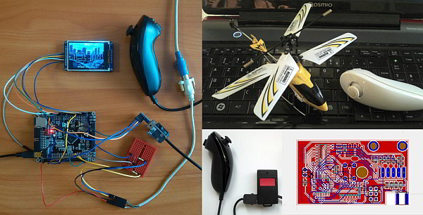
The Nintendo Wii Nunchuk was released in December 2006. It features an analog stick, two buttons, and a 3-axis accelerometer. Due to its low price (around $5 for a used or counterfeit Nunchuk) and I2C bus support, it became an easily accessible option for those looking to add an input device to their project without much hassle. Without further ado, let’s take a look at Nintendo Wii Nunchuk and some of the PCBA projects that utilize it.
What Is I2C And How It Works
Before examining the actual Nintendo Wii Nunchuk device, let’s examine the protocol that it uses.
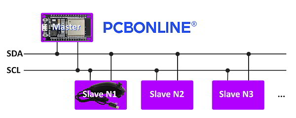
The Nintendo Wii Nunchuk benefits from employing the I2C protocol. I2C is a serial communication protocol that uses only two bidirectional lines – SDA (serial data) and SCL (serial clock).
The protocol operates in a master-slave configuration, where the master device initiates the communication and controls the clock signal on the SCL line. The master can read from or write to the slave devices by addressing them using unique 7-bit or 10-bit addresses.
Communication begins with the master generating a START condition by pulling the SDA line low while the SCL line is high. The master then sends the slave address along with a read/write bit to indicate the direction of the data transfer.
The slave device (the Nintendo Wii Nunchuk) responds by pulling the SDA line low to acknowledge (ACK) the address. The master and slave then exchange data bytes, with the receiver acknowledging each byte by pulling the SDA line low.
When the data transfer is complete, the master generates a STOP condition by transitioning the SDA line from low to high while the SCL line is high.
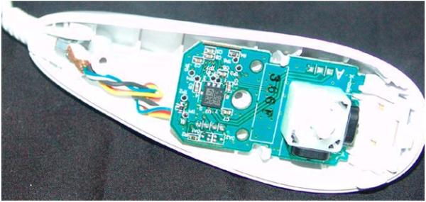
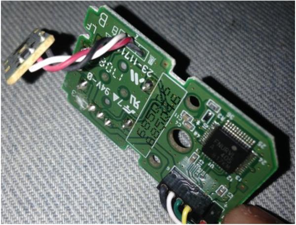
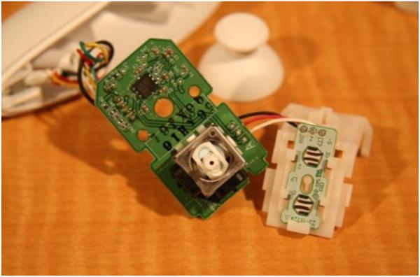
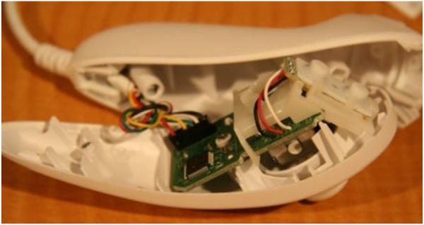
What’s Inside
As you can see in the photos below, the Nintendo Wii Nunchuk is a simple input device with only a few components inside. There’s not much there aside from the main PCB, two ICs, a 2-axis joystick, a PCB for the buttons, and a cable that goes out of the Nunchuk.
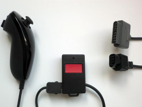
PCBA using Nintendo Wii Nunchuk: PCB Adapters
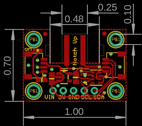
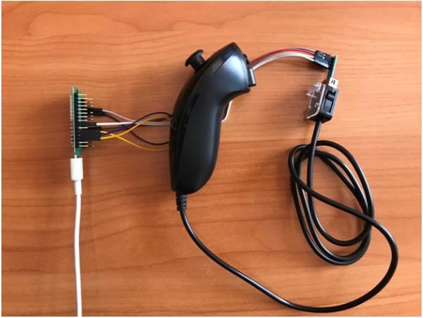
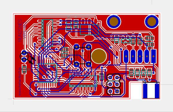
The high demand for the Nintendo Wii Nunchuk among makers led to the creation of simple PCBA adapters that simplify the integration of the Nintendo Wii Nunchuk into the devices that they make. Two such PCBA adapters, as well as the PCB template of one of them, are shown below.
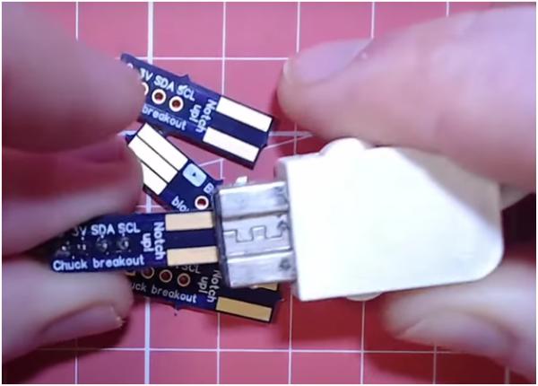
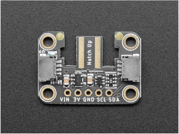
The Nintendo Wii Nunchuk became so popular that someone even made the dedicated PCBA adapters for the ESP8266 and the ESP32 that enable these boards to handle the Nunchuk with even more ease.
To create such an input PCBA device or making PCBAs using Nintendo Wii Nunchuk and other components, you can take your design into PCBA manufacturing to bring it into real devices.
Many makers also explore PCB manufacturing in the United States to ensure high-quality boards, faster turnaround times, and easier collaboration during the prototyping phase.
Below, you can see the capabilities of Nintendo Wii Nunchuk and its code examples so that you can integrate the Nintendo Wii Nunchuk into the PCB.
Nintendo Wii Nunchuk Compatibility
The table below shows what boards can handle the Nintendo Wii Nunchuk using the Nintendo Extension Ctrl library. A green cell on the right indicates that the board is compatible with the library, while a red cell denotes a lack of compatibility between the two.

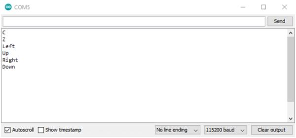
Code example
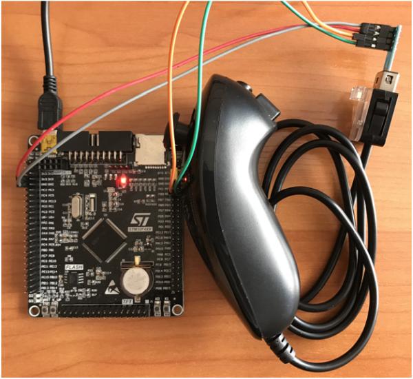
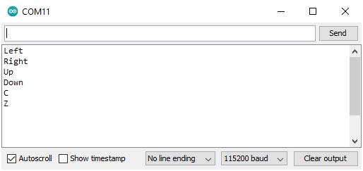
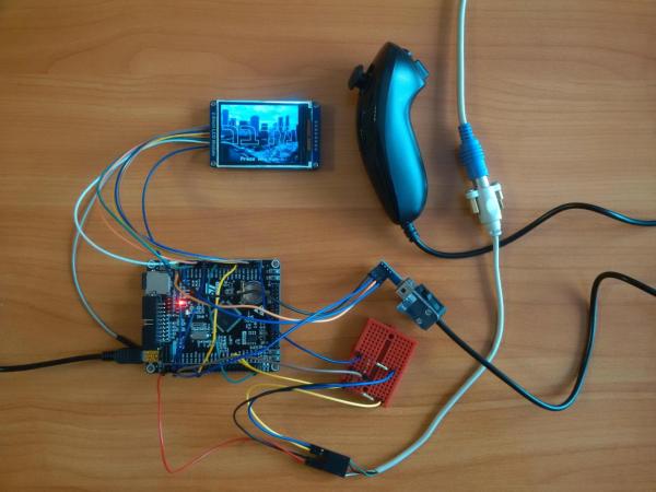
The following code example enables the board from the table above to handle the input from the Nintendo Wii Nunchuk. The connection tables for two boards are also included. Note that in order for this code to work, the NintendoExtensionCtrl library must be installed.
#include
Nunchuk wii_nunchuk;
bool pressed_c;
bool pressed_z;
bool held_left;
bool held_up;
bool held_right;
bool held_down;
byte threshold = 16;
void setup() {
Serial.begin(115200);
wii_nunchuk.begin();
while (!wii_nunchuk.connect()) {
Serial.println("Nunchuk not detected!");
delay(1000);
}
}
void loop() {
boolean success = wii_nunchuk.update(); // Get new data from the controller
if (!success) { // Ruh roh
Serial.println("Controller disconnected!");
delay(1000);
} else {
if (wii_nunchuk.buttonC() == true) {
if (pressed_c == false) {
Serial.println("C");
}
pressed_c = true;
} else {
pressed_c = false;
}
if (wii_nunchuk.buttonZ() == true) {
if (pressed_z == false) {
Serial.println("Z");
}
pressed_z = true;
} else {
pressed_z = false;
}
byte XAxis = wii_nunchuk.joyX();
byte YAxis = wii_nunchuk.joyY();
if (XAxis > (255 - threshold)) {
if (held_right == false) {
Serial.println("Right");
}
held_right = true;
} else {
held_right = false;
}
if (XAxis < threshold) { if (held_left == false) { Serial.println("Left"); } held_left = true; } else { held_left = false; } if (YAxis > (255 - threshold)) {
if (held_up == false) {
Serial.println("Up");
}
held_up = true;
} else {
held_up = false;
}
if (YAxis < threshold) {
if (held_down == false) {
Serial.println("Down");
}
held_down = true;
} else {
held_down = false;
}
}
}
| STM32 | Nintendo Wii Nunchuk |
| 3V3 | VIN |
| PB9 | SDA |
| PB8 | SCL |
| GND | GND |
| RTL8720DN | Nintendo Wii Nunchuk |
| 3V3 | VIN |
| GE2 | SDA |
| GE0 | SCL |
| GND | GND |
Projects Benefiting From Nintendo Wii Nunchuk
The Nintendo Wii Nunchuk is so convenient and easy to integrate that it became an integral part of the following projects.
Midbar (STM32F407VET6 Version) V2.0
The Midbar (STM32F407VET6 Version) V2.0 is a hardware data vault that utilizes the Nintendo Wii Nunchuk alongside the PS/2 keyboard as the input device. It can be controlled by either or both of them simultaneously. The 2-axis analog stick of the Nintendo Wii Nunchuk enables the user to move between the menu elements and input text by selecting the right character using the x-axis and adding or removing the letter using the y-axis. The “C” and “Z” buttons of that input device are used to move back and forth between tabs.
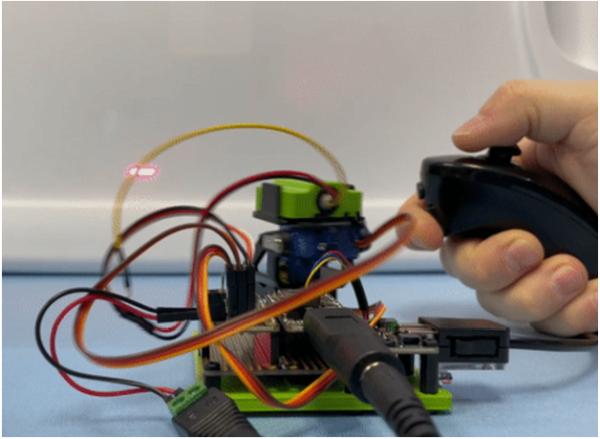
Nunchuk-controlled Helicopter
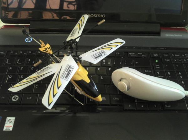
The Nunchuk-controlled Helicopter project involves using the Nintendo Wii Nunchuck as the controller for an RC helicopter. The “C” button of the Nunchuk is bound to the helicopter engine, while the 2-axis analog stick allows the operator to control the direction in which the helicopter flies.
Control a NES or SNES with a WII Nunchuk
The “Control a NES or SNES with a WII Nunchuk” is a simple converter that translates the input from the Nintendo Wii Ninchuk into the one that the classic Nintendo console understands. The custom PCB utilized by that project is shown below.
Wii Nunchuk Controlled Model Railroad
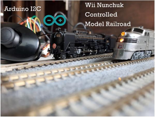
The “Wii Nunchuk Controlled Model Railroad” project utilizes the Nintendo Wii Nunchuk to control the complex railroad model, including the trains.
Nunchuck Controlled Laser Cat Toy
The “Nunchuck Controlled Laser Cat Toy” project utilizes the 2-axis analog stick of the Nintendo Wii Nunchuk to control where the laser beam points. Pretty convenient, isn’t it?
Wii Nunchuk as a USB HID controller
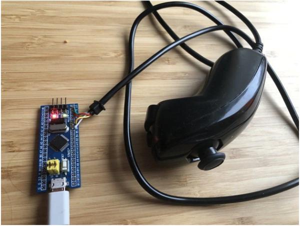
The “Wii Nunchuk as a USB HID controller” is a simple, STM32-based DIY adapter that turns the Nintendo Wii Nunchuk into an HID input device.
Conclusion
Nintendo Wii Nunchuk is an affordable and handy device that can simplify the development and debugging of your project, as you won’t need to spend time and resources designing and testing your own input device.
- What components are inside the Nintendo Wii Nunchuk?
The device contains a main PCB, two ICs, a 2-axis joystick, a PCB for buttons, and a cable. - How does the I2C protocol work with the Nunchuk?
The master device initiates communication using SDA and SCL lines, addressing the Nunchuk as a slave to exchange data bytes. - Can the ESP8266 and ESP32 handle the Nintendo Wii Nunchuk?
Yes, dedicated PCBA adapters were created specifically to enable these boards to handle the Nunchuk easily. - Which library is required to use the code example provided?
The NintendoExtensionCtrl library must be installed for the code to function correctly. - How are the C and Z buttons utilized in the Midbar project?
The C and Z buttons are used to move back and forth between tabs in the hardware data vault interface. - What is the function of the analog stick in the Helicopter project?
The 2-axis analog stick allows the operator to control the direction in which the helicopter flies. - Does the Nunchuk have a 3-axis accelerometer?
Yes, the Nintendo Wii Nunchuk features an analog stick, two buttons, and a 3-axis accelerometer. - What is the approximate price of a used or counterfeit Nunchuk?
A used or counterfeit Nunchuk costs around $5, making it an accessible option for makers. - How can the Nunchuk be used with a classic NES or SNES?
A custom PCB acts as a converter that translates Nunchuk input into signals the classic consoles understand. - Is the Nunchuk compatible with all microcontroller boards?
No, compatibility varies; the article provides a table showing specific green cells for compatible boards and red for incompatible ones.