Summary of Color Sensor Circuit with AT89S52 ADC0808
This project detects surface color (red, yellow, blue) by illuminating the surface with three colored LEDs, measuring reflected light with an LDR, converting the LDR voltage to digital with an ADC0808, and using an AT89S52 microcontroller to identify and display the detected color on a 2x16 LCD. The system includes LED brightness adjustment and resistors, a 12 MHz crystal, power regulator, and supporting capacitors and potentiometer.
Parts used in the Color Sensor Circuit with AT89S52 ADC0808:
- 3 x Ultra bright LED (red, yellow, blue)
- 3 × 220 ohm resistor
- 820 ohm resistor
- 1 k resistor
- LDR (light dependent resistor)
- AT89S52 microcontroller
- ADC0808 analog-to-digital converter
- 2x16 character LCD
- 10 k potentiometer
- 12 MHz crystal
- 2 × 20 pF capacitors
- 1 × 10 pF capacitor
- L7805 voltage regulator
This color of the surface color to red when you bring to the surface, a sensor to read the LDR, yellow, blue.Red, yellow and blue lights in different surface finishes as a different yansıtmalarını works by taking a foothold. Will be reflected from the surface to send 3 ledlights, this ledlerin to read the value of LDR, its resistance to read to see which is the LCD, LCD ledin brightness potentiometer and different values to adjust resistors, AT89S52 microcontroller and ADC.
LDR to turn digital information to analog information from analog to digital converter-integration used ADC0808.This project did a non-microcontroller with built-in ADC.I have the same circuit with an internal ADC controller could have an easier way.

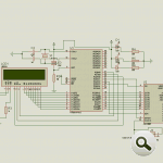
Color Sensor Circuit Diagram
Used Elements
- 3 x Ultra bright led
- 3 × 220 ohm resistor
- 820 ohm resistor
- 1 k resistor
- LDR
- AT89S52 microcontroller
- 2satır-16 characters LCD
- 2x20p, 1x10pf capacitor
- 12MHz chryristal
- 10 k potentiometer
- L7805 integrated
- ADC 0808
Operation Of The Circuit
Circuit mikrodenetleyicinin 18 and 19. uçarına XT oscillator is connected to the phone. The controller is needed to run the Palsy of the oscillator.Depending on the desired effect is poured directly from the source LEDs işığı. Adc 0808 of outputs connected to the P1 controller port on the mic. ADC0808 of analog input 8-bit numerical value digital information from döniştürüldükten and then P1 port.These numeric values are processed in the program of prayer and then sending that detect which color lcd to
Proteusta is not plotted on linear instead of LDR LDR of LDR. ADC 0808 of IN7 (analog input) to be converted to a numeric value from the tip of the voltage is done in the following way;
ADC is ultimately only a digital element portlarında unit produces the 1 ‘s and 0 ‘s information …
I can’t say that is sensitive to the values between 0 and 5v. ADC converts the information to a value from 0 to 255 and 256 volumes of information from the resolution.For this exercise, simply 8-bit adc.
As an example, it is worth to be read this * into * the adc Tip 2.1 volts, 107-108, there will be a number such as (2 * 256/5).
For more detail: Color Sensor Circuit with AT89S52 ADC0808
- How does the circuit detect different surface colors?
Colored LEDs illuminate the surface, reflected light is read by an LDR, converted by ADC0808 to digital values, and the AT89S52 processes these values to determine color. - Can the ADC0808 be omitted if the microcontroller has an internal ADC?
Yes, the article states a microcontroller with a built-in ADC would make the circuit easier and could replace the ADC0808. - What microcontroller is used in the project?
The project uses an AT89S52 microcontroller. - How is the LDR signal converted for the microcontroller?
The LDR voltage is input to ADC0808 which converts the analog voltage (0–5V) into an 8-bit digital value (0–255) for the microcontroller. - What display is used to show the detected color?
A 2x16 character LCD is used to display the detected color. - How is LED brightness adjusted in the circuit?
LED brightness is adjusted using a potentiometer and different resistors as described in the article. - What clock source does the microcontroller use?
The AT89S52 uses a 12 MHz crystal oscillator connected to its XT pins. - What resolution does the ADC0808 provide?
The ADC0808 provides an 8-bit resolution, converting voltages into values from 0 to 255. - Which ADC input is used for the LDR in the example?
The article indicates using ADC0808 IN7 as the analog input for the LDR. - What power regulator is used in the circuit?
An L7805 voltage regulator is used for power regulation.