
Summary of Circuit and firmware to support Seiko-Epson G1216B1N000 dot graphics display using ATtiny2313
This article describes a project to drive a Seiko-Epson G1216B1N000 LCD display using an AT90S2313 microcontroller for waveform visualization. The author selected the display based on resolution, availability, documentation, ease of interface, and cost. Challenges included the display's split 64x64 architecture and pin limitations, requiring a custom Right/Left control pin implementation which introduced artifacts that needed careful software handling.
Parts used in Seiko-Epson LCD Drive Project:
- Seiko-Epson G1216B1N000 LCD display module
- AT90S2313 microcontroller
- Bias supply circuit
- Serial interface circuit
- Right/Left control pin configuration
A serial interface and bias supply for the Seiko-Epson G1216N000 using an AT90S2313 because there just aren’t enough applications examples for this display on the web.
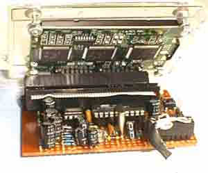
I was looking for an LCD display that I could use to display waveforms on the workbench. The selection criteria for the display module itself was straight forward:
1. Dot graphic with sufficient resolution to display a simple waveform,
2. Available for fast delivery,
3. Have sufficient documentation available online to design with,
4. Be easy to interface to mechanically, electrically, and firmware wise, and
5. Have a low price.
The Seiko-Epson G1216B1N000 was selected, apparently meeting all criteria, but I was unable to get it to work until Jesper Hanse kindly sent me his driver for the driver for the display in his VAMPP4 TAMPP (Yet Another MP3 Player) and comparing his code with my code, I found some mistakes I had made.
The display is a pretty old transflective gray mode TN LCD design with ok, but not great contrast. Its contrast is better than the screen shot above. The display’s saving grace is that appeared to meet all of the primary criteria. The code to drive it was complicated somewhat by the fact that the 8 bit interface appears as two 64×64 displays for the left and right hand sides, and since I was determined to control it with an AT90S2313, I was a pin short of being able to have separate select pins for the left and right displays, and so implemented a Right/Left control pin, which produced some artifacts in the display, and avoiding these made it necessary to carefully code around them.
For more detail: Circuit and firmware to support Seiko-Epson G1216B1N000 dot graphics display using ATtiny2313
-
Why was the Seiko-Epson G1216B1N000 selected?
It met criteria including dot graphic resolution, fast delivery, available documentation, easy interfacing, and low price. -
What problem did the author face with the initial display selection?
The author could not get the display to work until comparing code with Jesper Hanse's driver for the VAMPP4 TAMPP project. -
How is the display physically structured internally?
The 8 bit interface appears as two separate 64x64 displays for the left and right hand sides. -
Why was a Right/Left control pin implemented?
The AT90S2313 was a pin short of having separate select pins for the left and right displays. -
What issue arose from using a single control pin for both sides?
Implementing a Right/Left control pin produced artifacts in the display that required careful coding to avoid. -
What type of LCD technology is the G1216B1N000?
It is an old transflective gray mode TN LCD design with ok but not great contrast.
