A high-end keyboard synthesizer may cost around $3,000. In this project, we aim to create a very basic keyboard with analogous functionality for less than $75 dollars. Obviously, the quality of the sounds, number of instruments one can play, playback length, and lots of other features are going to be inferior or unimplemented. However, it will still be impressive (and fun!) for us to create a functional keyboard for such little cost in such little time.

A high-end keyboard synthesizer may cost around $3,000. In this project, we aim to create a very basic keyboard with analogous functionality for less than $75 dollars. Obviously, the quality of the sounds, number of instruments one can play, playback length, and lots of other features are going to be inferior or unimplemented. However, it will still be impressive (and fun!) for us to create a functional keyboard for such little cost in such little time.

- 1.Play notes in real-time from 4 different instruments
- 2.Record those notes as they are played
- 3.Play back a single track of recorded notes as any instrument
- 4.Play back all 4 tracks of recorded notes as any mix of instruments
From an implementation perspective, we needed to accomplish:
- 1.Instrument synthesis through a PWM output running at 62.5kHz
- 2.Reading commands from a keypad
- 3.Reading keyboard input from a keyboard/keypad
- 4.Storing notes for each track
- 5.Printing to an LCD
- 6.Managing the state machine that would control the keyboard
- 7.Reading input/calculating output on time
Now let’s get into the technological backgrounds for each:
- 1.Instrument synthesis through a PWM output running at 62.5kHz
A Pulse Width Modulated signal uses a rectangular wave and a low-pass filter to generate sine waves. The idea is that while a regular square wave would be filtered by the low-pass filter, a rectangular wave with varying duty cycle (seen in pink on the left) would cause slow transitions in the average of the output (seen in green on the left). Since a slow transition would be passed by the low-pass filter, we can produce a sine wave with a digital signal. For our keyboard, we use a low-pass filter with a corner frequency on the order of 100Hz to filter the PWM frequency and to create a more pleasing sound.
The frequency synthesis is done through a table of PWM samples for one cycle of a sine wave (or frequency modulated sine wave, or an addition of multiple sine waves at different harmonics). The frequency of the note heard is changed by how fast we run through the PWM samples.
- 2.Reading commands from a keypad
We used a 16-key 8-pin keypad (seen on left) to read commands. Each button on the keypad would issue one command. The keypad is wired as a matrix, so we can reliably read one key at a time by determining which column and row are connected.
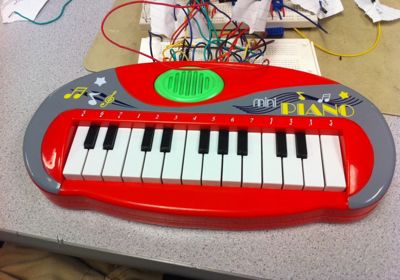
- 3.Reading keyboard input from a keyboard
We wired the keyboard as 23 independent switches. The STK-500 would not have that many free pins, however, so we used priority encoders to encode the key signals. We split the keys into 3 sections of 8 and used 8-3 encoders to get 4 outputs for each section (12 outputs total). We combined these signals through basic digital logic to get 6 outputs that we could hook up to the STK-500.
- 4.Storing notes for each track
We used a simple C array to store the key numbers we captured during recording. Note that this is an array and not a matrix; due to the limited number of connections on the STK-500, we cannot capture every piano key at the same time, so we only play/record one note at a time. We capture ~10 notes/sec and record up to ~13 seconds, resulting in 128-length arrays for each track.
- 5.Printing to an LCD
We used a 16×2 LCD to display messages to the user. Conveniently, we were able to use a library (lcd_lib.h) that could print strings to the LCD. So our output consisted of updating our global output strings when necessary, and regularly writing those strings out to the LCD.
- 6.Managing the state machine that would control the keyboard
Our keyboard is controlled by a state machine that keeps track of what is going on at any given time. Most transitions between states are triggered by commands. We wrote a function handle_keypress(..) to examine what key was pressed and what state the keyboard is in and then transition to a new state and run any necessary code (for example, when a user presses a key to Delete all tracks, we have to run code that will erase the notes data).
- 7.Reading input/calculating output on time
Everything we needed this keyboard to do was time-sensitive. To simplify our lives, we used the TinyRealTime kernel. Everything except the PWM calculation and output is done by tasks that run periodically. For example, during recording, we capture notes at ~10 notes/sec. This is done by running a task that executes ~100ms. The code to schedule this task can be seen on the left.

Since TinyRealTime uses the Mega644’s timer1, we use timer0 for the PWM calculation and timer2 for the PWM output. The PWM output runs at 62.5kHz, but the calculations take longer, so we run those with timer0 in an interrupt that runs every 8kHz. This combines the benefits of a high PWM frequency (don’t have to worry about filtering an audible frequency) and slower calculation frequency (takes less CPU time by running less frequently).
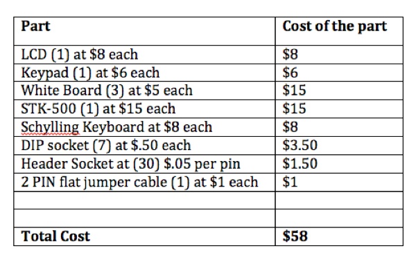
Parts List:
For more detail: A Keyboard Synthesizer Workstation using Atmega644