Our acoustic wayfinding device utilizes ultrasonic range finders and haptic feedback to facilitate indoor navigation for the visually impaired. The technique of acoustic wayfinding uses auditory cues, such as sounds from the natural environment or sounds created artificially, to determine an individual’s surrounding physical space for the purpose of navigation. Our device is an automated and subtle implementation of this technique that uses pulses of inaudible (to humans, at least) frequencies in the ultrasonic range as opposed to taps on the floor with a cane or clicking noises made by the tongue; our device also works in noisy environments where it is typically difficult to discern auditory cues.
Our device consists of an ergonomic head-mounted navigation system with a wearable tactile sensor connected via a long flexible wire. Our device instructs the user to turn either left or right depending on the presence of obstacles in the device’s field of view. The device is supplemented with a tactile sensor that mimics a “Hoover” cane (a white cane commonly used by the visually impaired as a mobility tool) which the user can use to scan for obstacles not detectable by the head-mounted sensors. This hands-free device is battery powered which allows users to navigate confidently without loss of mobility.
High Level Design
The ultrasonic wayfinder is comprised of two main wearable sub-systems: a head-mounted navigation sub-system, and a hand-mounted tactile sensor sub-system (see Figure 1 for a high-level overview). The head-mounted navigation device is used for spatial sensing and directional navigation, while the hand-mounted tactile sensor is used for sensing obstacles in close proximity to the user below eye-level, similar to a “Hoover” cane.
The head-mounted navigation system consists of two ultrasonic rangefinders and two vibrating motor discs. The rangefinders are capable of detecting obstacles up to 6.45 meters away with a field of view of about 120 degrees. The head-mounted system instructs the user to turn left or right using one of the two motors mounted on the back of the user’s head.
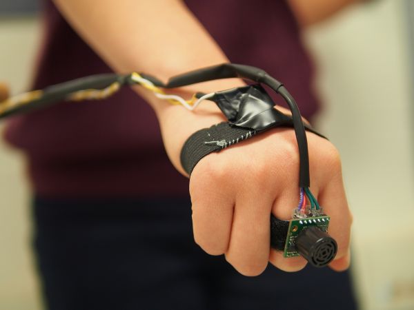
The hand-mounted tactile sensor consists of one ultrasonic rangefinder and one motor that the user can wear on his or her hand. The tactile sensor allows the user to “scan” for obstacles below eye-level (typically out of the range of the head-mounted sensors) by sweeping his or her hand laterally, similar to how one would use an assistive cane. The rate at which the motors pulse is proportional to the distance of the obstacle from the user — the closer the object, the more rapid the pulses.
Rationale and Inspiration
While brainstorming ideas for our final project, we first browsed previous work done on Hackaday. We were inspired by a project that used a robot as a safe and cost-effective alternative to guide dogs (see link). This device helps the visually impaired avoid obstacles using 3D mapping from four cameras. Like a guide dog, the robot pulls the user in different directions to avoid detected objects. We thought this was a great idea, but thought it would be better to have a wearable guidance system that would be more subtle, less cumbersome, and have less interference with the user’s mobility.
We decided to create a head-mounted system for object detection to facilitate indoor navigation using the technique of acoustic wayfinding. With two ultrasonic rangefinders mounted on the head and a third rangefinder in the user’s hand, this system provides an intuitive set of haptic feedback instructions to tell the user what direction to walk towards. These haptic instructions are provided by two vibrating motors in the headpiece and a third motor on the user’s hand.
Past ECE 4760 project groups have created similar devices that utilize ultrasonic rangefinders for navigation. However, many of these past devices have several shortcomings of their own, such as limited range, limited field of view and noisy sensor outputs leading to incorrect feedback. Furthermore, none of the previous projects have devices that could detect obstacles that are most hazardous to a visually impaired person — obstacles below the eye-level that could potentially cause the visually impaired person to trip and fall.
As such, we developed a device that combine various aspects of past projects that worked well in a more cohesive and ergonomic package. On top of that, we extended the device with an extended tactile sensor that allows the user to detect low-lying obstacles in an intuitive and familiar manner by mimicking the use of a “Hoover” cane. We also decided to use haptic feedback as we did not want to interfere with the hearing of the user — visually impaired people are typically more reliant on their sense of hearing in navigating the physical space. Haptic feedback would also allow our device to be used in noisy environments.
Background Math
The ultrasonic rangefinders work by emitting an ultrasonic pulse and timing the duration it takes to receive the pulse reflected off an obstacle. As the speed of sound in air is approximately 340m/s (disregarding variations in humidity, pressure, interference, etc), the distance of the obstacle can be determined by (340 * (measured duration))/2.
Logical Structure
Our device uses the TinyRealTime kernel to provide real-time functionality; this allows our device to perform certain tasks simultaneously, such as allowing the user to use the extended tactile sensor independently of the head-mounted navigation system.
There are real-time tasks for the sequential reading of each ultrasonic rangefinders and two other separate tasks for the navigation logic — one for instructing the user to either turn left or right, and another for the tactile sensor.
All the readings are median filtered so as to remove discrete noises caused by interference (typically from external sources) or noises in the sensor circuit.
Hardware Tradeoffs
We decided to use commercial ultrasonic rangefinders with a large range and a wide beam pattern at the expense of resolution and cost as they would be most suited for our device — the large range ensures that we can detect obstacles far away and the wide beam pattern gives us a greater field of view.
We initially had the third ultrasonic rangefinder mounted on the head tilted towards the ground to detect objects below eye-level and sudden changes in elevation, which could be indicative of a flight of stairs. However, we found that we got erratic readings that depended greatly on the nature of the obstacle surface.
We decided to use ultrasound as opposed to infrared for ranging, since ultrasonic characteristics are best suited for our device. Our device requires larger ranges than most infrared transmitter/sensor setup can detect, and was designed for use in indoor environments where interference from other infrared-emitting sources can pose a problem.
Software Tradeoffs
The median filter we employed uses a window of size 3. While a larger filter size would be more effective in removing noise, it would require more computational complexity (especially since the filter is applied to all the rangefinder readings). Furthermore, we found that a size 3 median filter was sufficient in removing most of the erroneous readings.
Existing Products
There have been similar head-mounted assistive devices developed in the past, such as SonicGuide (developed in 1974) and the KASPA system (developed in 2002). KASPA is an updated version of SonicGuide, using ultrasound mounted on a headband instead of on spectacle lenses. Both systems use haptic feedback to communicate with the user, similar to our device.
We also found that a past ECE 4760 project, “Ultrasonic Haptic Vision System”, used a similar concept using an ultrasonic rangefinder and small vibrating motors.
Our system differs from these other devices in execution and concept. Our device supplements the head-mounted navigation system with the use of a hand-mounted tactile sensor, which acts as a virtual cane, which is intuitive for visually impaired individuals.
Software Design
Initialization and Calibration
As shown in Fig 2 above, upon powering on the device, the program first initializes the ADC and TRT kernel, and creates the necessary semaphores and real-time tasks. The ADC is initialized by configuring the appropriate registers, mainly to left-align the ADC values in the data registers (to convert the measurements from 10-bits to 8-bits as we did not need 10-bits resolution and it was easier to read off one register) and to set the prescaler to 32 (which we determined experimentally to provide the best compromise between sampling frequency and resolution for our purpose).
The program then enters the calibration mode in which it determines the threshold for the tactile sensor based on the height of the user. The user is required to hold the tactile sensor by his or her side while the program performs the initial calibration. The program takes three calibration readings at around 140ms apart, and then chooses the the median value as the calibrated value to remove any outlying readings that may arise due to interference or noise.
The tactile sensor threshold is determined to be sqrt(2) * calibrated value as we assume that the user will most often be holding the tactile sensor at a 45 degree angle (like how one would when using an assistive cane) such that the hypotenuse would be given by sqrt(2) * (height of triangle).
Obtaining Range Information from Sensors
There are three separate real-time tasks for reading from each of the ultrasonic rangefinders from the microcontroller’s ADC inputs.
The main issue we had to deal with was the simultaneous use of all three ultrasonic rangefinders. Semaphores are used to ensure that the rangefinders are ranging sequentially such that they do not interfere with each other (e.g. one rangefinder receiving another rangefinder’s reflected pulse). Delays are used to ensure that the rangefinders have sufficient time to range; particularly, a delay of 50ms is used as the rangefinders require 49ms to obtain a range reading.
Range information is obtained from the sensors by calling the adc_read function which selects the correct ADC pin by setting the right bit values in ADMUX, starts the conversion, and then returns the 8-bit range value from the register ADC. The 8-bit range value from the ADC is converted to distance in meters using the following equation:
![]()
The first term converts the ADC bit value proportionately from 0 to 255 (since the value is 8-bits) to 0 to 5V. The second term converts the voltage to distance in inches — according to the MB1000 datasheet, the analog output from the sensor corresponds to (Vcc/512)V per inch. Finally, the third term converts the distance reading from inches to meters.
Median Filtering
All ultrasound rangefinder readings are median filtered (with a filter of size 3) to remove impulse noises. The median filtering was effective as most of the noises encountered in the ranging data were impulse noises (see Figure 3).
We found that the most frequent cause of these noise is the sudden changes in ranges detected when the rangefinder ranges multiple objects of different distances. For instance, when the rangefinder is pointed slightly off-centered towards a person standing 3m away from the sensor (with a wall 2m behind the person), the range data will change abruptly from 3m to 5m, creating spikes in the range data similar to those that we see in Figure 3 above.
Another common source of impulse noises are the unintended reflections caused by overestimating the distance of an object when the reflected pulse bounces off the ground before reaching the rangefinder.
Wayfinding Logic
There are two real-time tasks responsible for the wayfinding aspect of the device: the navigation and tactile sensor logic.
The navigation logic checks for the presence of obstacles in the fields of view for the left and right rangefinders. If an object is found within our defined threshold of 2m in either field of view, the corresponding motor will buzz (obstacle on right side -> buzz right, obstacle on left side-> buzz left), indicating to the user the direction of the obstacle. If obstacles are detected by both the left and right rangefinders, then the user will be notified of the direction of the obstacle closer to the user (which is likely the obstacle more critical or hazardous to the user).
The tactile sensor logic checks for the presence of obstacles within the threshold as determined by the calibration process. Obstacles at a range below this threshold are obstacles that would typically be detected when a visually impaired person scans his or her immediate surroundings using a “Hoover” cane, i.e. objects that are large enough to cause the user to trip and fall, or objects that can collide with the user. The tactile sensor logic also scales the intensity of the vibrations proportionately with the proximity of the obstacles.
Both the navigation and tactile sensor logic functions linearly interpolate the intensity of the vibrations according to the distance of the obstacles from the sensor. This is done by varying the duration of each pulse using the equation
![]()
where the values of the multiplier were experimentally determined to be 30 for the navigation logic and 20 for the tactile sensor logic. This was chosen such that the minimum detectable range of approximately 0.15m will give 200ms and 133ms for the multiplier values of 30 and 20 respectively. Longer pulse durations (and hence higher pulse intensities) were used for the head-mounted motors as compared to the hand-mounted motors as we found that the head is less sensitive to vibrations compared to the hand.
Real-time Scheduling
All the ranging and navigation tasks are in real-time so that the device gives the illusion that the head-mounted and hand-mounted sensors are working independently and simultaneously.
All the real-time tasks but the navigation logic are executed with the deadline equaling the release time. This means that the tactile sensor logic task and all three ranging tasks run in the order in which they are released (i.e. not in a true “real-time” fashion) and have priority over the navigation logic. The navigation logic is also running at a frequency of 300ms compared to 250ms for all the other tasks. This is because the navigation logic can still function fairly accurately while using range data that are slightly “old”.
The ranging tasks for all three rangefinders repeat at every 250ms. We determined experimentally that this is approximately the minimum time the task requires to complete the ranging (which takes 49ms according to the datasheet), to convert the range to meters, and to save the range for median filtering.
Parts List:
| Part Number | Vendor | Quantity | Price | Total Cost |
| ATMega1284 | Lab stock | 1 | $5 | $5.00 |
| Maxbotix LV-MaxSonar-EZ0 (x3) | Adafruit | 3 | $24.95 | $74.85 |
| Vibrating Mini Motor Disc (Part No. 1201) | Adafruit | 3 | $1.95 | $5.85 |
| Head harness | Pre-owned | 1 | $1 (estimated) | $1.00 |
| Large Solder Board | Lab stock | 1 | $2.50 | $2.50 |
| Custom PCB | Lab stock | 1 | $4 | $4.00 |
| Header Pin | Lab stock | 36 | $0.05 | $1.80 |
| Capacitors | Lab stock | 11 | $0 | $0.00 |
| SPDT Switch | Lab stock | 1 | $0 | $0.00 |
| 2N3904 NPN BJT | Lab stock | 3 | $0 | $0.00 |
| Resistors | Lab stock | 5 | $0 | $0.00 |
| 9V Battery Holder | Lab stock | 1 | $0 | $0.00 |
| 9V Battery | Amazon | 1 | $2 | $2.00 |
| Wire | Lab stock | 3’ | $0 | $0.00 |
| Velcro | Lab stock | 4” | $0 | $0.00 |
| White foam | Lab stock | 3” | $0 | $0.00 |
| Total cost | $97.00 |
For more detail: Acoustic Wayfinder Using Atmega1284