Summary of ADJUSTABLE CONSTANT CURRENT LASER DIODE/LED DRIVER
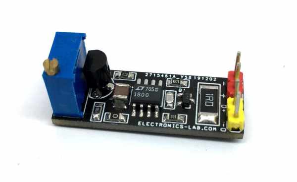
This article describes a DIY adjustable constant current driver circuit designed to safely operate low-cost laser diodes and LEDs. The author built this module to replace unstable series resistors, offering precise current control from 0 mA to 115 mA using an LT1800 op-amp. The project includes an onboard multi-turn potentiometer for accurate calibration and operates on a 5V DC supply.
Parts used in the Adjustable Constant Current Laser Diode/LED Driver:
- LT1800 precision operational amplifier
- Multiturn potentiometer (trim-pot)
- Laser diode
- Current meter
- 5V DC power source
- Circuit board
I was testing a couple of low-cost laser diodes that come from china and I was wondering why those diodes don’t have any protection/driver circuitry. Those diodes come with a simple series resistor for current control which is not a good idea nor stable. Laser diodes are harmful and should have some sort of constant current circuit as a basic protection for the laser diode. As result, I built this circuit which provides highly accurate current control. The module is a great tool to drive low-cost laser diodes with superb accuracy. This circuit can drive diode starting from 0 mA to 115mA, usually, these cheap diodes require around 30mA current. The project has an onboard multi-turn potentiometer to adjust the output current with great accuracy. It is advisable to turn the trim-pot to zero level and then hook-up the laser diode.
To test a diode with this circuit is very easy, the first step is to set the trim-pot to 0 level (fully turned CCW), power the board with 5V DC, check the voltage on the centre pin of trim-pot it should be 0 Volt, then connect the laser diode with a current meter in series, slowly turn the trim-pot Clockwise to set the current as per requirement. Cheap laser diodes take approx. 30mA current.
The driver can also be used to drive LEDs, operating voltage of this circuit is 5V DC, and maximum load 115mA. Project built using LT1800 precision op-amp.
The LT1800 is a low power, high-speed rail-to-rail input, and output operational amplifier with excellent DC performance. The LT1800 features reduced supply current, lower input offset voltage, lower input bias current, and higher DC gain than other devices with comparable bandwidth. The LT1800 has an input range that includes both supply rails and an output that swings within 20mV of either supply rail to maximize the signal dynamic range in low supply applications. The LT1800 maintains its performance for supplies from 2.3V to 12.6V and is specified at 3V, 5V and ±5V supplies. The inputs can be driven beyond the supplies without damage or phase reversal of the output.
Read more: ADJUSTABLE CONSTANT CURRENT LASER DIODE/LED DRIVER
- Why do low-cost laser diodes often lack protection circuitry?
The article states that cheap diodes typically come with only a simple series resistor for current control, which is described as not being a good idea nor stable. - What is the operating voltage range for this driver circuit?
The operating voltage of this circuit is 5V DC. - How can I safely test a laser diode with this module?
First set the trim-pot to zero level, power the board with 5V DC, verify 0 Volts at the center pin, connect the diode with a current meter in series, and slowly turn the pot clockwise to set the required current. - Can this circuit be used to drive LEDs?
Yes, the driver can also be used to drive LEDs. - What is the maximum load current this circuit can handle?
The maximum load is 115mA. - What specific type of operational amplifier is used in this project?
The project is built using the LT1800 precision op-amp. - Why is a constant current circuit necessary for laser diodes?
Laser diodes are harmful and should have some sort of constant current circuit as a basic protection because they require highly accurate current control. - What is the recommended initial step before connecting a laser diode?
It is advisable to turn the trim-pot to zero level and then hook-up the laser diode.