The story so far
Welcome to the never ending saga of Andy and his reflow controllers. About a year ago I published a project writeup showing how I built a PID-based reflow controller. It featured a 640×360 graphical LCD from the Sony U5 Vivaz mobile phone and was all-surface mount. It worked well and continues to serve me well to this day but I always thought that there were improvements that I could make in several areas.
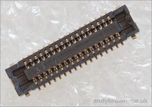
Firstly, there’s no reason why it should have been all surface-mount. The LCD in particular has a 0.4mm connector that many people will find very hard to solder by hand. After all, presumably you’re building a reflow controller to help solve that very problem. Chicken and egg.
MAINS_L and MAINS_N are the live and neutral mains terminals, respectively. SW_IN and SW_OUT are the terminals that connect to the on-off switch. The maximum current rating for this design is 8A so the switch must be rated accordingly and should contain an embedded fuse because there’s no provision for one on the board itself. There’s not much chance of a standard household fuse blowing before the triac is destroyed but it should blow before anything really bad, such as a fire, starts.
C4 is an X-class film capacitor rated at 275VAC. It’s used for emissions filtering and can be considered optional if you’re not bothered about that.
You have your fuse for overcurrent protection and now you have R3, a varistor for overvoltage protection. Under normal operating conditions the varistor has a very high resistance but when a voltage spike is encountered the varistor quite suddenly becomes very low resistance, protecting the triac from the spike. I’ve never personally witnessed a triac failure but I’m informed that they can fail explosively so it’s good to protect them if we can.
OVEN_L and OVEN_N are the live and neutral output terminals to the halogen oven. The triac controls when these terminals are switched on and off. Speaking of the triac…
For more detail: An Android Reflow controller that anyone can build

