Summary of ATmega64 Development Board
This Atmel ATmega64 development board offers a robust platform for custom AVR firmware and microprocessor education, surpassing breadboard setups with organized PCB headers. Designed before Arduino's local availability in the Czech Republic, it integrates essential modules like an RTC, temperature sensor, EEPROM, and USB converter. The board supports LCD and 7-segment displays, features PWM control via an N-FET, and includes ISP programming capabilities for efficient testing and debugging of embedded systems.
Parts used in the Atmel ATmega64 Development Board:
- Atmega64 Microcontroller
- DS3231 RTC Real-time IC
- DS1820 1-Wire Temperature Sensor
- 24AA00SN I2C EEPROM
- FT232RL USB/RS232 Converter
- 8x Buttons
- 16x LED Lights
- LCD Display 16×2 Connector
- 7-segment-LED Display
- N-FET for PWM
- ISP Programming Connector J2
- Voltage Regulator
This project is a development board for Atmel ATmega64 microcontroller and can be used to easily develop custom AVR firmware or as an introduction board to microprocessors and programming. A development board is better to be used instead of a breadboard setup as it facilitates the connection of the different components using PCB headers. The project was designed at the time when the Arduino board wasn’t available in the Czech Republic and is equipped with different modules.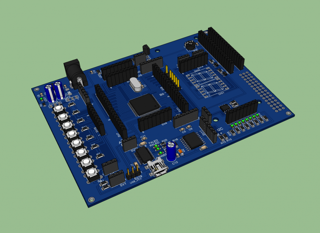
Description
The features of this board are:
- Atmega64 – all the ports available through pins, a different crystal can be connected (optional frequency crystal)
- DS3231 RTC, real-time IC / I2C
- Temp. DS1820 1wire Temp. sensor
- EEPROM 24AA00SN / I2C EEPROM
- USB Port FT232RL USB/RS232 converter
- Buttons 8x -16x LED
- Connect LCD Display 16×2
- 7segment-LED Display
- N-FET For PWM
- ISP Programming connector
All module pins are labeled for easy connection with the processor and there are separate connectors and jumpers for all MCU ports so you can easily connect, test and debug your firmware. Also there is an ISP programming connector J2.
The PCB can be powered via the USB connector, or with a voltage regulator through an external adapter.
Schematic
The full schematic is shown below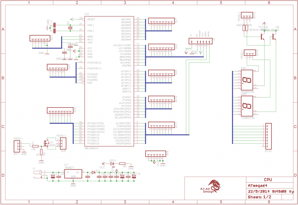
For more detail: ATmega64 Development Board
- What is the primary purpose of this development board?
The board facilitates the development of custom AVR firmware and serves as an introduction to microprocessors and programming. - Can different crystals be connected to this board?
Yes, a different crystal can be connected as an optional frequency crystal. - How is the PCB powered?
The PCB can be powered via the USB connector or through a voltage regulator using an external adapter. - Does this board include a real-time clock module?
Yes, it is equipped with a DS3231 RTC real-time IC that uses I2C communication. - What type of temperature sensor is integrated into the project?
The board features a DS1820 1-wire temperature sensor. - Is there support for connecting an LCD display?
Yes, the board has connectors specifically designed to connect a 16×2 LCD Display. - How does the board handle PWM functionality?
An N-FET is included on the board specifically for PWM operations. - Can the board be used for ISP programming?
Yes, the board includes an ISP programming connector labeled J2.