
Summary of DigiPot – Rotary Encoder Digital Potentiometer
This project is a DigiPot featuring a rotary encoder connected to an ATmega microcontroller. It displays values on a 7-segment display, indicates status via LEDs, and outputs analog voltage or digital data via I2C/Serial. The system supports autonomous operation or host control, with capabilities for chaining multiple units and selecting communication protocols via jumpers.
Parts used in the DigiPot:
- Rotary Encoder (TW-700198)
- Microcontroller (ATmega8/168/328)
- 7-segment displays
- Status LEDs
- n-FET transistors
- Anode resistors
- Coupling capacitors (C1-C8)
- Crystal oscillator
- MCP4821 DAC
- ISPtouch connector
- Jumpers
- Headers for chaining
Description
The “potentiometer” is actually a rotary encoder (TW-700198) connected to a microcontroller that reads the signal from it and convert it to a value that is displayed on 7-segment displays. The value also is sent via i2c/spi/serial/usb to the host. Also 3 LED and included for status indication.
The board is planned to either be operated in an autonomous mode where the display is updated by the board itself or in a host mode where the host is telling the board what to display.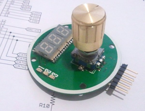 DigiPot is a digital potentiometer using a rotary encoder as input along with a 7 segment display that show the current pot value.
source code isn’t available yet :.
A “Rotary Encoder” aka “Quadrature Encoder” is sending pulses to the microcontroller that will determine how the user is turnin the knob and calculating a current value for it. This value will be digitally sent to the host via i2c or another serial protocol. At the same time an analogue voltage will be generated and be presented at a output.
Possibly also the value could be sent to a digital potentiometer chip like a MCP4551 as well to set a resistive value.
An ATmega8/168/328 is selected as the microcontroller since it has enough i/o for this project. I also choose to use a ISPtouch connector for as the programming interface.http://dangerousprototypes.com/?p=62605
Specifications:
- Three digits display with movable decimal point.
- Three status leds.
- Quadrature encoder with button-functionality.
- Communicate with host via i2c/serial-ttl.
- Multiple units can be chained.
- The value can be output as an analogue voltage with 12 bit resolution.
Parts description
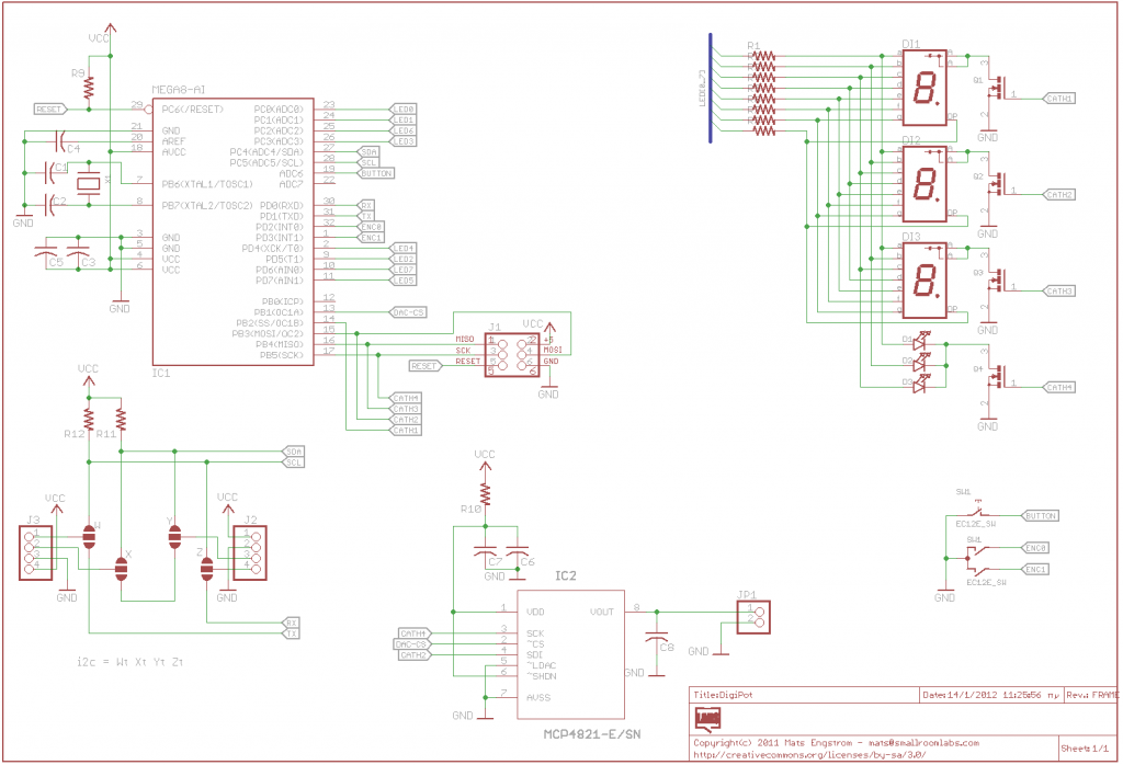
Starting from top there’s 4 n-fet transistors for muxing the cathodes of the displays and leds. Then there are 8 anode resisors. The atmega with C3/C4/C5 decoupling caps. The crystal with C1/C2 load caps is followed by R10/C7/C6 that is a filter for the supply to the mcp4821 12 bit dac.
Below the atmega there are some jumper for selecting if the units is to communicate with serial uart or i2c. The two 4 pin headers can be used to chain multiple units either by i2c as a bus, or a daisy-chain with serial, if serial the last unit in the chain must be looped.
R9/R11/R12 is pullups for i2c and reset. The 2-pin header is analogue voltage out and is filtered by C8. The 5 pads on the bottom is the programming header.
Schematic
For more detail: DigiPot – Rotary Encoder Digital Potentiometer
- What type of encoder is used?
A Quadrature Encoder or Rotary Encoder sends pulses to determine knob rotation. - How does the board communicate with a host?
The board communicates via I2C or Serial-TTL protocols. - Can multiple units be connected together?
Yes, multiple units can be chained using I2C as a bus or serial daisy-chain. - What is the resolution of the analog output?
The analog voltage output has a 12-bit resolution. - Which microcontrollers are selected for this project?
An ATmega8, ATmega168, or ATmega328 is selected due to sufficient I/O. - How is the communication mode selected?
Jumpers below the ATmega select between serial UART or I2C communication. - What component generates the analog voltage?
The MCP4821 12-bit DAC generates the analog voltage output. - Is source code currently available?
No, the source code is not available yet.
