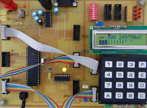
PCB and the schema (sch) P-CAD 2004 Schematic drawings prepared by V18.00.2690 also c languagecode through the test has been prepared with an alternative link.
ATMEGA-32 Development Board
Power 7V to 12V (4mm sockets) protected against reverse polarity
Visualization by 8 LEDs Statements of eight logic outputs (your choice according the HE10 connector wiring entry port, PortBait, PORTC, PORTD output keyboard or encoded)
8 inverters to generate the logic levels on inputs
2 adjustable knobs to generate tension on the analog inputs
4 HE10 connectors to connect the ports ATMEGA32 keyboard on the screen LCD, the LEDs, the reversers to generate logic levels or other cards
One for connecting your ISP (programming ATMEGA32)
JTAG connector for connecting HE10 1 (emulation ATMEGA32)
For more detail: Atmel Test Card using ATmega32 microcontroller

