Summary of An AVR microcontroller based Ethernet device
The article introduces the ENC28J60 Ethernet chip, a 28-pin SPI interface device by Microchip designed for microcontrollers. It simplifies building networked devices without complex hardware or separate serial buses. The project demonstrates a generic circuit using an AVR microcontroller to control a relay via UDP commands, featuring minimal external components like a crystal and transformer.
Parts used in the ENC28J60 Ethernet Device:
- ENC28J60 Ethernet chip
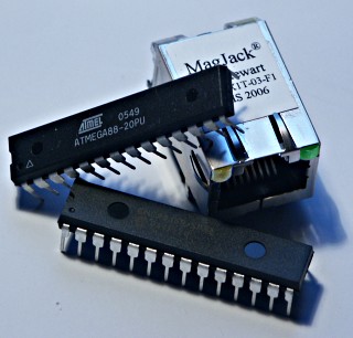
- AVR microcontroller (Atmega88)
- Crystal oscillator
- Ethernet transformer (magnetics)
- Relay (6V compatible)
- Diode D1 (for coil protection)
- LED-B
- Connector CONN3
Ethernet has traditionally been a quite complex interface. All Ethernet chips until today had 100 pins or more, where difficult to find in small quantities and difficult to use from a small microcontroller with little memory. Microchip has changed the world with their new ENC28J60 Ethernet chip!
The ENC28J60 is a small chip with 28 pins only and has a SPI interface which is easy to use from any microcontroller.
This opens a whole world of completely new applications. You can easily build small devices which can be spread all over the house and simply connected to ethernet.
You don’t need anymore a separate serial connection or other bus. Everything can be easily connected via Ethernet. Distance is no longer a limiting factor.
Even WIFI connectivity is possible because you can connect the devices to a wireless bridge.
All hardware components are available from shop.tuxgraphics.org. The software and circuit diagrams are available for free (GPL V2 license).
Introduction to the ENC28J60 Ethernet controller
The ENC28J60 from Microchip is a fantastic chip. It has Tx/Rx, MAC and PHY in one small chip. There are very few external parts. Basically just a crystal and an Ethernet transformer, aka magnetics. All this comes in an convenient 28-pin DIP package. Easy to solder and perfect for hobby applications.
The microcontroller can then control any hardware you like: You can attach some sensor (light, temperature), you can switch on an off something you can attach a LCD display, etc…
The Plan
In this first article we will build a generic hardware with lots of IO interfaces and analog to digital converter inputs. We will however only control a small relay to switch on or off something. In later articles we can then use the same hardware and do more complicated things.
The main purpose is to show here the circuit diagram and explain the software. We use a UDP application to send commands to the microcontroller. Those commands will then cause the microcontroller to switch on or off the relay.
It think it will be possible to even implement TCP. The current UDP software is less than 3k bytes and that is not even half of the memory on an Atmega88. TCP would then allow us to control the device via a web browser. I have however not tried it yet.
The circuit diagram
Here is the circuit diagram. Most of it is very straight forward and standard for the ENC28J60. The polarity of LED-B is important as it determines the duplex operation of the chip. Standard Half-duplex is what makes most sense for a device which will send and receive only rather little traffic.
A relay can be connected to connector CONN3. Note the diode D1. It is not useless and it is not the wrong way round in the circuit diagram even though it looks like that. It is there for those who plan to connect a small 6V relay on that output. It protects the whole circuit against the possibly very high voltages which can be induced by the coil of a relay.
For more detail: An AVR microcontroller based Ethernet device
- What makes the ENC28J60 easier to use than traditional Ethernet chips?
The ENC28J60 has only 28 pins and uses a simple SPI interface, unlike older chips with 100+ pins. - Can I connect these devices over long distances?
Yes, distance is no longer a limiting factor as everything connects via Ethernet. - Does this setup support wireless connectivity?
Yes, you can connect the devices to a wireless bridge to enable WIFI connectivity. - What protocol is currently used to send commands to the microcontroller?
The current software uses a UDP application to send commands. - Is it possible to implement TCP for web browser control?
It is thought to be possible, but the author has not tried implementing TCP yet. - Why is diode D1 included in the circuit diagram?
It protects the circuit from high voltages induced by the coil of a small 6V relay. - What duplex mode is recommended for low traffic devices?
Standard Half-duplex makes the most sense for devices sending and receiving little traffic. - How much memory does the current UDP software consume on an Atmega88?
The current UDP software is less than 3k bytes.