
Summary of AVR Thermometer using AT90S2313 microcontroller
This article describes building an "AVR Thermometer" using an AT90S2313 microcontroller, a 4-digit common anode LED module, and a DS1820 temperature sensor. The project utilizes a homemade ISP cable for programming and runs C code compiled with AVR CodeVision. The circuit connects the LED segments to PORTB via resistors and digit control to PORTD, while the sensor links to PD1 with a pull-up resistor. The software employs a foreground-background scanning method to display temperature on the LEDs.
Parts used in the AVR Thermometer:
- AT90S2313 microcontroller chip
- 4-digit common anode LED multiplex module
- DS1820 temperature sensor chip
- 220 Ohms resistors
- 4.7k pull-up resistor
- PNP small signal transistor
- Universal PCB
- 10-pin header for STK200 compatible downloader
- S1-S4 optional keypad switches
- Homemade ISP cable
Introduction
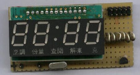
I bought the LED module from BanMor’ last week, just 30Baht. The moduleprovide a prewired multiplex of 4-digit common anode LED, that’s great.See the soldering pad of these signal in the 1st picture below. I thought,my friend gave me the AT90S2313 chip, and with a simple homemade ISP cableand a free software AVR ISP downloader, so we don’t need the device programmer.Also I got the DS1820 from my friend. So I spent my freetime weekend puttingthem together, “the AVR Thermometer”. The 2nd picture shows a samplecircuit using universal PCB, see the upper right, it was 10-pin headerfor STK200 compatible downloader. Of course the LED module was designedfor CLOCK display, so you may interested in writing C program for bothClock and Temperature display after built this project.
Circuit
The circuit diagram is straight forward, similar to 89C2051Clock Circuit. PORTB sinks forward current of each LED segmentthrough a 220 Ohms resistor. The common anode pin for each digit is controlledby PORTD, i.e., PD2-PD5. The PNP transistor can be any types of small signaltransistor. S1-S4 are optional keypad. Also PD6 is optional output. Allof LEDs are driven with sink current.
The temperature sensor chip, DS1820 is connected to PD1 with a 4.7kpull-up resistor. The example of circuit uses only one sensor, you maytie multiple sensors on the same line and modify the program to read itwith the help of internal chip ID.
J3 is AVR ISP/STK200 compatible downloader. See the pin designationand build the cable from Experimentingthe AT90S8535 with CodeVisionAVR C Compiler
The software for download the hex code, thermo.hexto the 2313 chip, can get from ATMEL FTP website here ATMELAVR ISP.
Software
The source porgram was written in C language and compiled with AVR CodeVisionC compiler. Actually my first try used the AT90S8535, then I moved theC code from 8535 to 2313 with a bit modification.
The program was foreground and background running, or interrupt driven.The background task is forever loop scanning 4-digit LED.
main()
{
while (1)
{
scanLED(); // run background task forever
}
}
The function scan display was borrowed from 89C2051 Clock controller.(Actuallyno need any modifications if we use a preprocessor to define such I/O port.)
#define segment PORTB
#define LED_digit PORTD
void scanLED() /* scan 4-digit LED and 4-key switch, if key pressedkey = 0-3
else key = -1 */
// adapted from 89C2051 project if needs scan key, find onebit input port
{
char i;
digit = 0x20;
key = -1;
for( i = 0; i < 4; i++) /* 4-DIGITscanning */
{
LED_digit = ~digit; /* send complement[digit] */
segment = ~heat[i]; /* send complement[segment] */
delay_ms(1); /* delay a while */
segment = 0xff; /* off LED */
// if ((PORTD & 0x10)== 0) /* if key pressed P3.4 became low */
// key =i; /* save key position to key variable*/
digit>>=1; /* next digit */
}
}
for-loop statement provides 4-cycle scanning from digit0 to digit3.First we activate digit control line by sending complement of digit variable.Follow with segment data from heat[i] array. The delay 1ms provides enoughtime for electron to jump back to ground state converting to electromagneticradiation. Then turn off before changing digit. The digit data is thenshifted to the right one bit. Similarly for the next digit.
For more detail: AVR Thermometer using AT90S2313 microcontroller
-
How was the AT90S2313 chip programmed?
The chip was programmed using a simple homemade ISP cable and free software called AVR ISP downloader without needing a dedicated device programmer. -
What compiler was used for the source program?
The source program was written in C language and compiled using the AVR CodeVision C compiler. -
How are the LED segments driven in the circuit?
PORTB sinks forward current for each LED segment through a 220 Ohm resistor. -
Which pins control the common anode of the digits?
The common anode pin for each digit is controlled by PORTD, specifically pins PD2 through PD5. -
Can multiple temperature sensors be connected?
Yes, you may tie multiple sensors on the same line and modify the program to read them using the internal chip ID. -
Where can the download software be obtained?
The software for downloading the hex code to the chip can be found on the ATMEL FTP website under the AVR ISP section.
